
Method for determining the distance between a base station and a mobile object, in addition to a base station and identification system for a method of this type

Inactive Publication Date: 2005-05-12
SIEMENS AG
View PDF8 Cites 23 Cited by
  • Summary
  • Abstract
  • Description
  • Claims
  • Application Information

AI Technical Summary

Benefits of technology

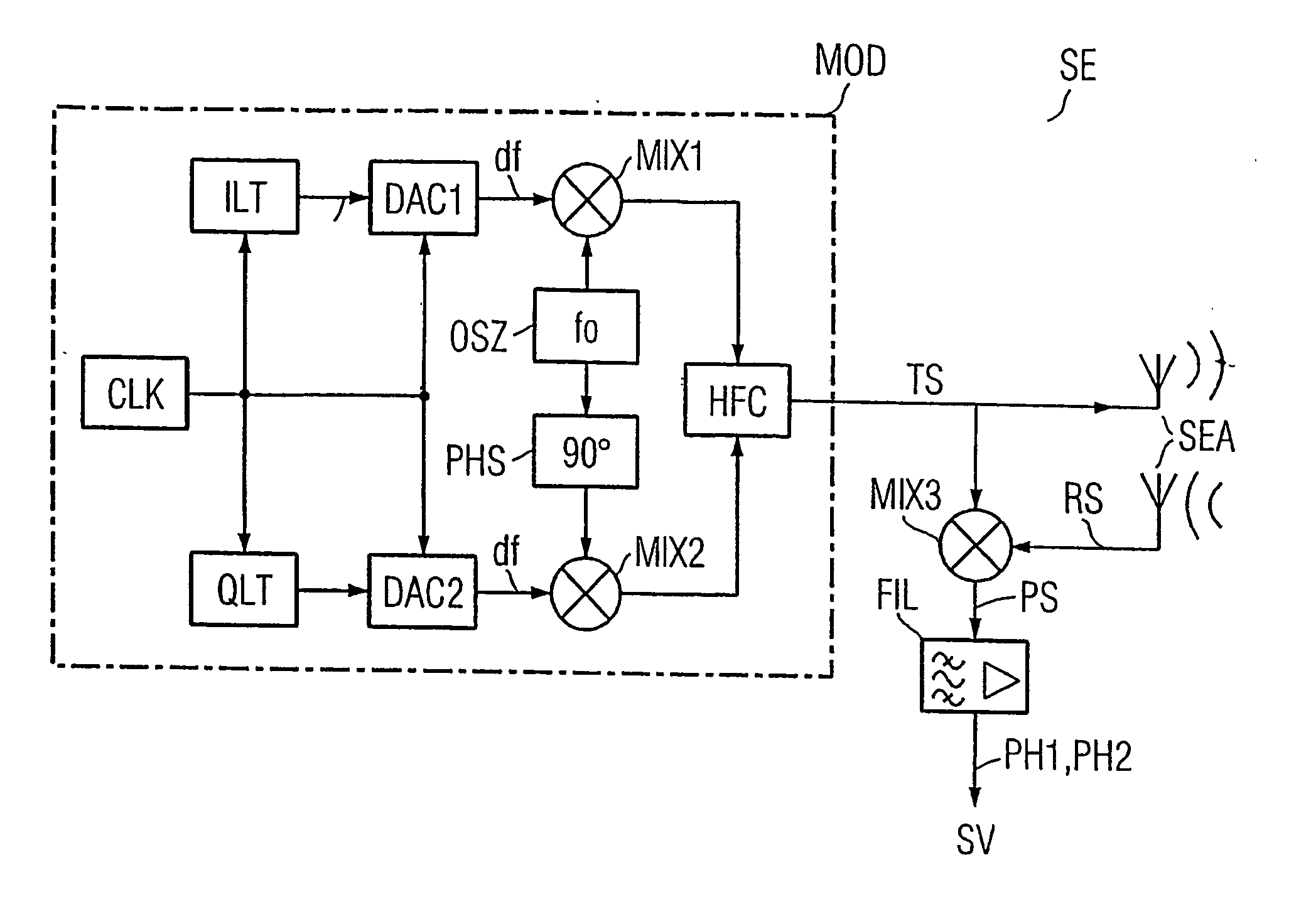
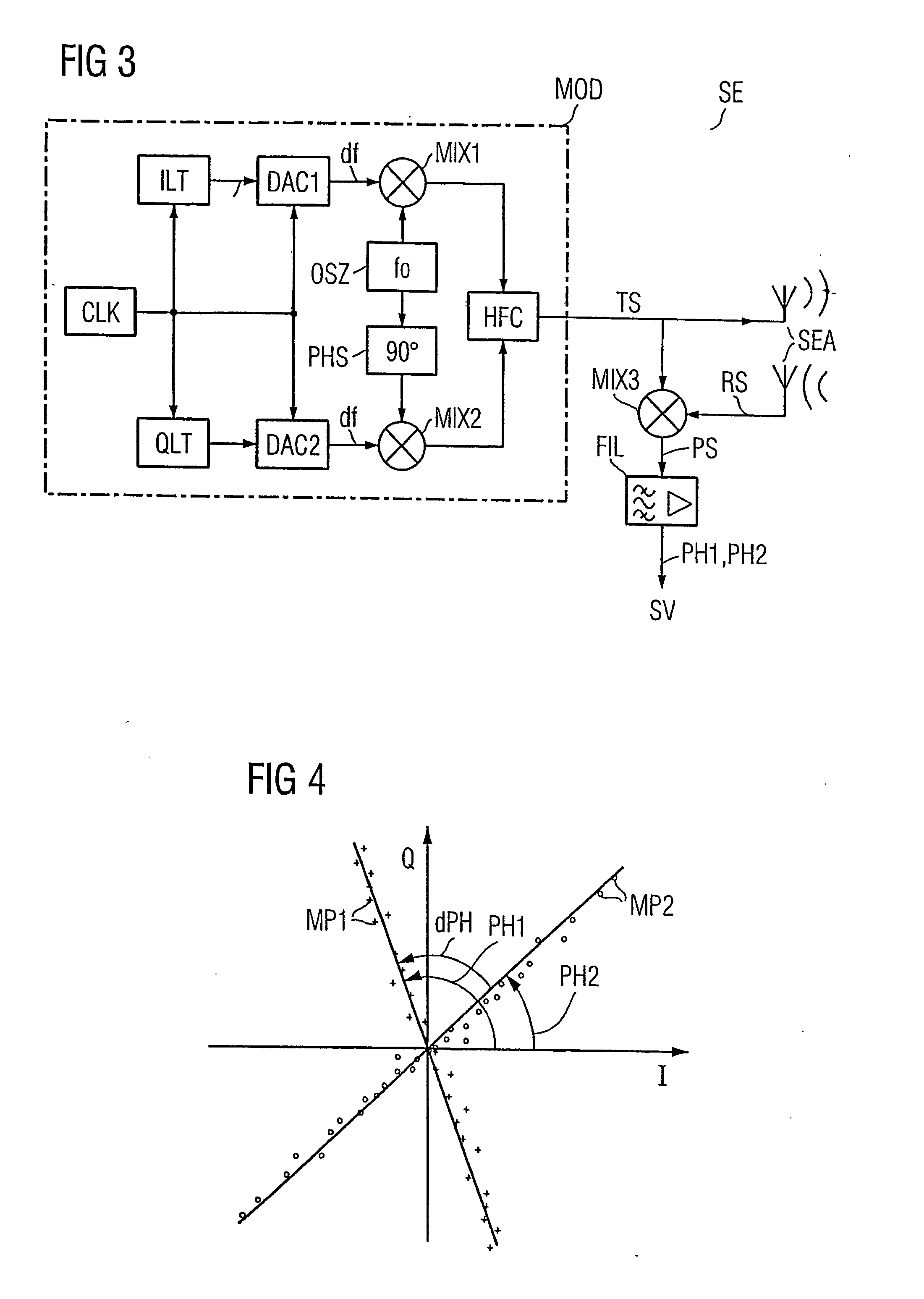
[0010] As a result, the phase of the two IQ-modulated HF carrier base frequencies in the HF carrier signal is identical in the base station. This has the advantage that the phase jumps, which usually occur when the frequency is changed, are avoided. An additional measurement on the transmitter in the base station and the required measuring time are advantageously eliminated.
[0013] This makes it possible to increase the measurement accuracy. The distance can thus be determined very precisely.
[0014] In one variant of the method, the base station is a read / write device and the mobile object is a mobile data memory. Matching their frequencies ensures good backscattering properties for determining the distance.
[0021] An important advantage is that the carrier phase can be measured using existing circuit components, such as the PLL for HF carrier frequency modification and the IQ modulator for data modulation. As a result, the distance can be measured with sufficient accuracy without added complexity of electronic circuit components.

Problems solved by technology

The undesirable interactions could lead to overshoots between the individual base stations and the corresponding mobile data memories.
Frequencies generated in a conventional manner to determine distances can be subject to significant measurement inaccuracies.
This requires additional complex circuitry.

Method used


Image

  • Method for determining the distance between a base station and a mobile object, in addition to a base station and identification system for a method of this type
  • Method for determining the distance between a base station and a mobile object, in addition to a base station and identification system for a method of this type
  • Method for determining the distance between a base station and a mobile object, in addition to a base station and identification system for a method of this type

Examples


Embodiment Construction

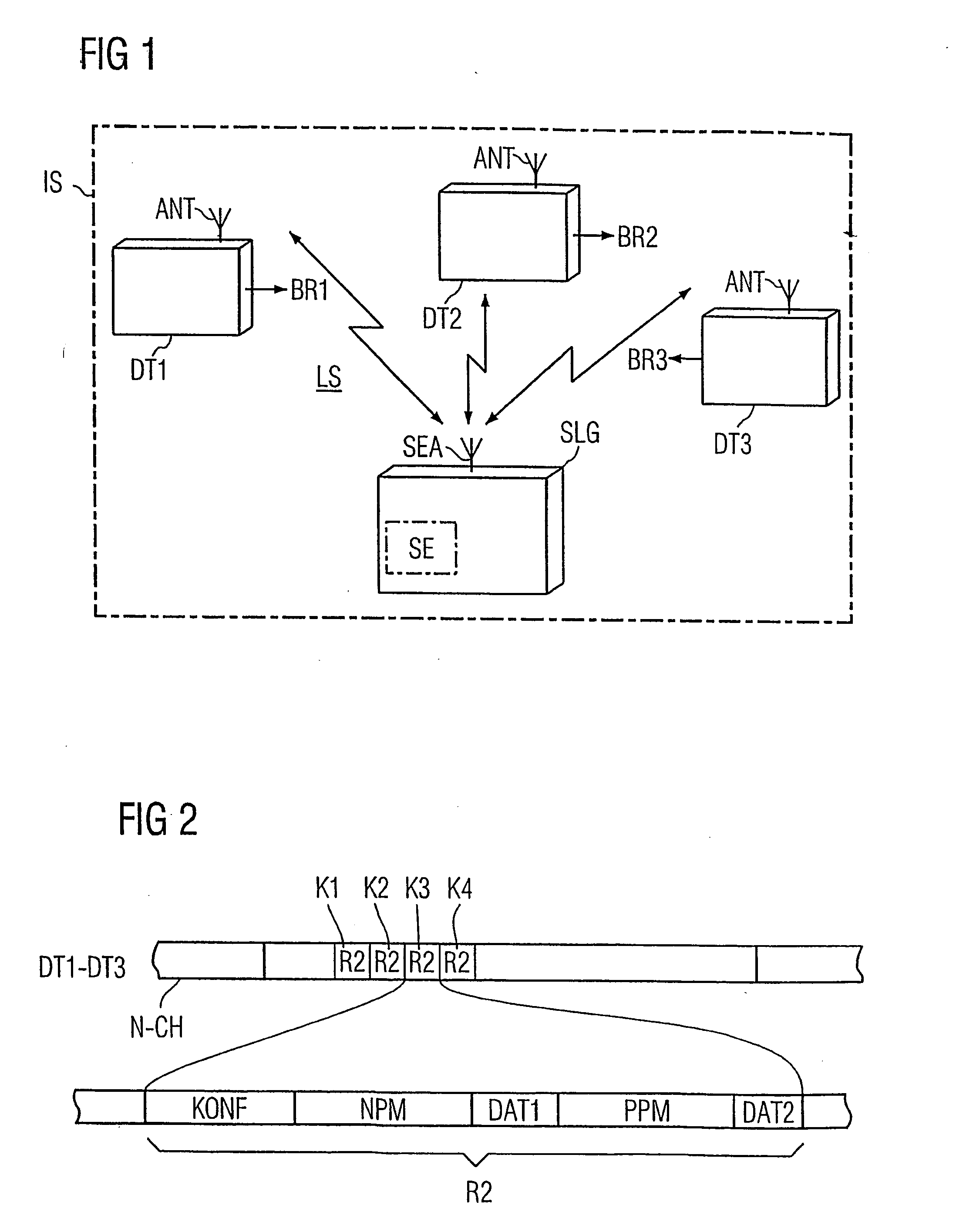
[0027]FIG. 1 shows an example of an identification system according to the present invention. The exemplary identification system includes a base station SLG (which can be a read / write device) and a plurality of mobile data memories DT1-DT3. An wireless interface LS is provided between the data memories DT1-DT3 and the base station SLG The mobile data memories DT1-DT3 each move in the direction shown. The different possible movement directions BR1-BR3 of the mobile data memories DT1-DT3 are shown in the figure by way of example.

[0028] The data memories DT1-DT3 and the base station SLG each have an antenna ANT, SEA, respectively for data communication there between. In the base station SLG, the dash-dotted rectangle indicates a transceiver SE, which is used to implement the method according to the invention.

[0029]FIG. 2 shows an exemplary data structure corresponding to a transmission channel N-CH for communication between the mobile data memory DT1-DT3 and the read / write device SL...


PUM


Abstract

A method for determining the distance between a base station (SLG) and a mobile object (DT1-DT3). A HF carrier frequency and an offset frequency (df) are predetermined for a QAM modulation. The HF carrier frequency is increased and decreased by the offset frequency in sequence over time in such a way that the HF carrier base frequencies (fo+df, fo−df) resulting in an HF carrier signal (TS) thus modulated exhibit an identical phase when the frequency is changed. The HF carrier signal is subsequently transmitted and simultaneously mixed (MIX) with an HF carrier signal (RS) that has been backscattered by the mobile object to obtain a carrier phase signal (PS). The corresponding carrier phase (PH1, PH2) for the two HF carrier base frequencies is determined in sequence over time. The difference (dPH) between these phases is used to calculate the distance between the base station and the respective mobile object.

Description

[0001] This is a Continuation of International Application PCT / EP03 / 014014, with an international filing date of Dec. 10, 2003, which was published under PCT Article 21(2) in German, and the disclosure of which is incorporated into this application by reference.FIELD AND BACKGROUND OF THE INVENTION [0002] The invention relates to a method for determining the distance between a base station and a mobile object. Further, the invention relates to such a method in an identification system having at least one mobile data memory which is attached to objects and acts as a mobile object for recording object-related status and / or process data. For example, the mobile object could be attached to objects in shipping, transport and / or production systems. The invention also relates to an identification system, a base station, etc., associated with such a method. [0003] Methods for distance determination are known in the conventional art. For example, RADAR is a well known method for determining ...

Claims


Application Information

Patent Timeline
IPC IPC(8): G01S7/288G01S13/34G01S13/74G01S13/75
CPCG01S13/348G01S2007/2886G01S13/75G01S13/74G01S7/2886
Inventor GILA, JANOSKONRAD, WOLFGANGRENNER, ALEXANDER
Owner SIEMENS AG
Learn More