Backlight device and liquid crystal display device therewith

a liquid crystal display device and backlight technology, applied in the direction of lighting and heating apparatus, instruments, mechanical apparatus, etc., can solve the problems of affecting the optical characteristics of the liquid crystal display device, and the above-mentioned fitting method is insufficient to overcome the increasingly striking effects

Inactive Publication Date: 2005-05-12
SHARP KK
View PDF1 Cites 44 Cited by
  • Summary
  • Abstract
  • Description
  • Claims
  • Application Information

AI Technical Summary

Benefits of technology

[0010] In view of the conventionally encountered problems discussed above, it is an object of the present invention to provide a backlight device and a liquid crystal display device in which, even when an optical sheet expands or contracts as the ambient temperature varies, the optical sheet does not wrinkle or warp.

Problems solved by technology

This causes the optical sheet 2 to be deformed with wrinkles, badly affecting the optical characteristics of the liquid crystal display device.
Considering the current trend toward increasingly large liquid crystal display devices in the fields of television monitors and the like, the fitting method described above is insufficient to overcome the increasingly striking effects of the concentration of stresses resulting from the expansion and contraction of an optical sheet.

Method used


Image

  • Backlight device and liquid crystal display device therewith
  • Backlight device and liquid crystal display device therewith
  • Backlight device and liquid crystal display device therewith

Examples


first embodiment

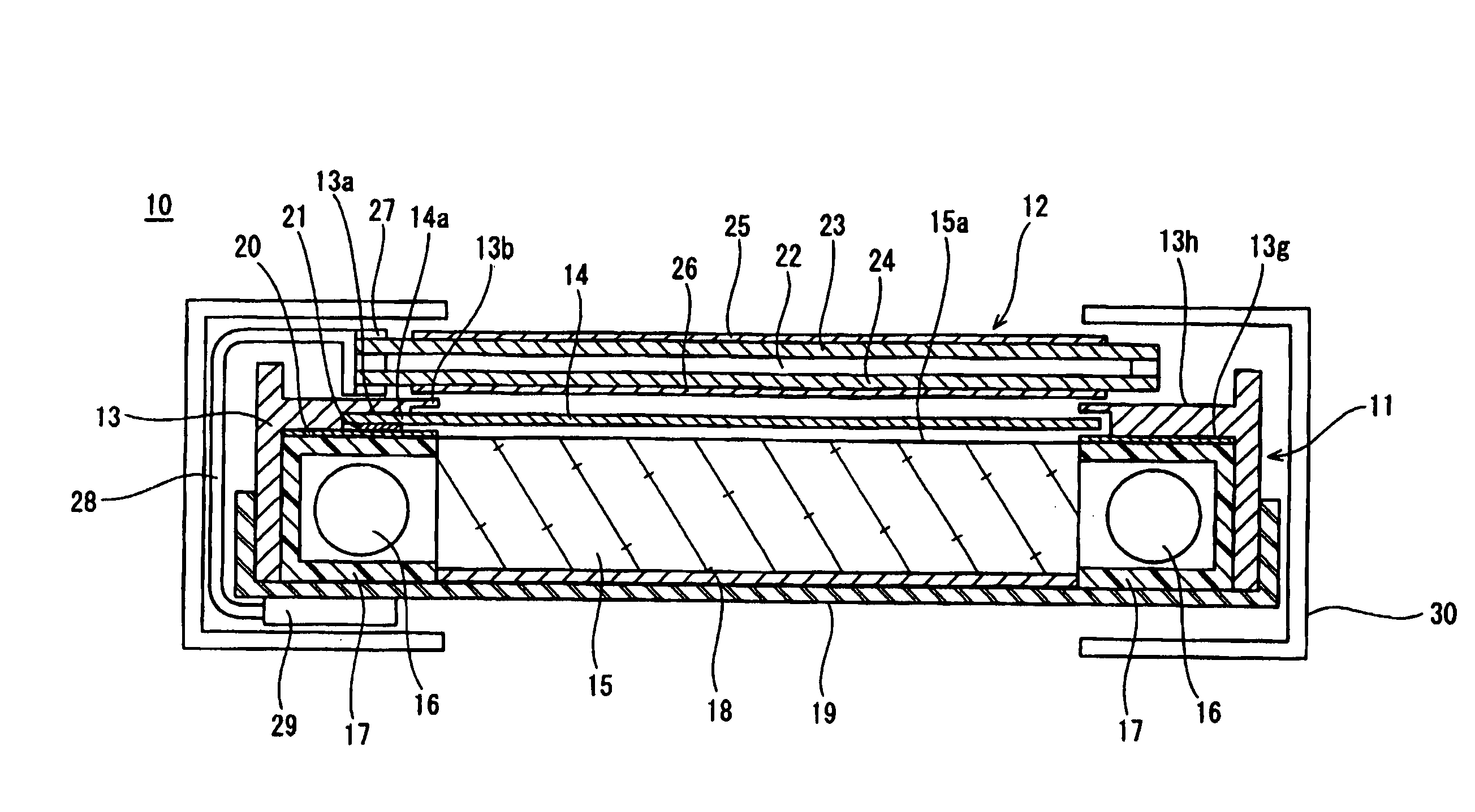
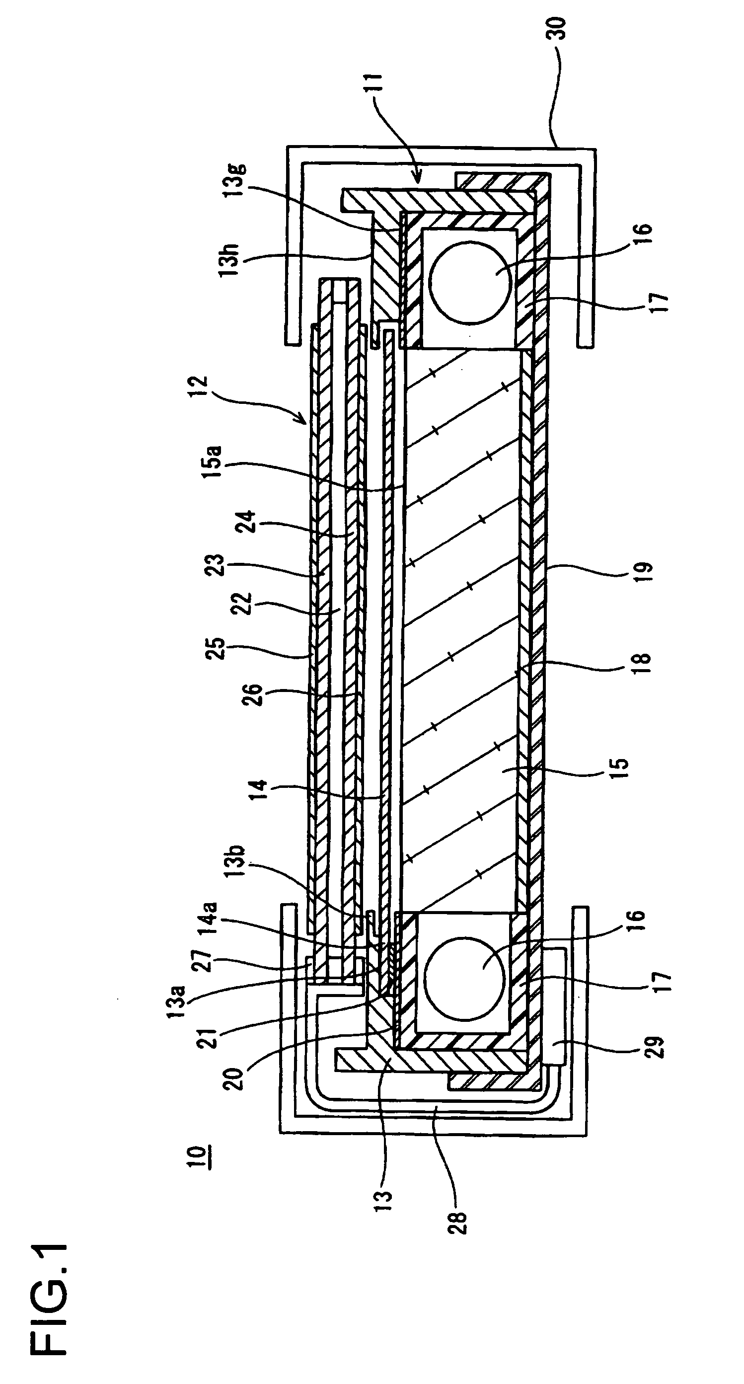
[0053]FIG. 1 is a sectional view schematically showing the backlight device and the liquid crystal display device of the invention. In the liquid crystal display device 10 shown in this figure, a backlight device 11 having an optical sheet laid on the light-emitting side thereof and a liquid crystal panel 12 are held together by a metal bezel 30.

[0054] The backlight device 11 includes: a case 19 having a C-shaped cross-section; a reflective sheet 18 laid over the floor surface of the case 19 and formed of PET foam; a rectangular light guide plate 15 arranged on top of the reflective sheet 18 and formed by molding acrylic resin; a pair of linear light sources (cold cathode fluorescent lamps) 16 arranged along opposite ends of the light guide plate 15 so as to face each other; lamp holders 17 having a C-shaped cross-section and arranged to surround the linear light sources 16; an optical sheet 14 arranged on the light-exit side of the light guide plate 15; a rectangular frame 13 that ...

second embodiment

[0068]FIGS. 8 and 9 show the backlight device and the liquid crystal display device of the invention. In the following description, no explanations will be repeated of such features as are found also in the previously described embodiment, and chiefly the differences therefrom will be discussed.

[0069] The frame 33 has a rectangular frame portion 33f and a stepped portion 33b. The stepped portion 33b is thinner than the frame portion 33f, and projects inward from the inner edge 33f-1 of the frame portion 33f In the frame portion 33f, a recessed portion 33a is formed that has the same shape as in the previously described embodiment. On the side where the recessed portion 33a is formed, on both sides thereof, positioning projections 33c are formed that each have the same shape as in the previously described embodiment.

[0070] The optical sheet 34 is rectangular, and has a projecting portion 34a that projects outward from the center of one side 34c thereof. The tip portion of the projec...

fourth embodiment

[0078] Moreover, in this embodiment, as in the fourth embodiment described above, as shown in FIG. 13, the depth of the recessed portion 53a of the frame 53 may be made approximately equal to the thickness of the projecting portion 14a of the optical sheet 14.

[0079] In all the embodiments described thus far, the optical sheet is pressed by the pressing member so that the optical sheet is supported by being held between the frame and the pressing member. Alternatively, it is also possible to form a hole in the optical sheet and a pin-like member on the frame so that the optical sheet is supported on the frame as a result of the pin-like member being put through the hole. FIG. 14 shows an example of this type of supporting structure.

[0080] In FIG. 14, substantially at the center of the floor surface of the recessed portion 13a of the frame 13, a cylindrical pin-like member 70 is formed to project upright therefrom. The height of the pin-like member 70 is equal to the depth of the rec...


PUM

PropertyMeasurementUnit
thickaaaaaaaaaa
thicknessaaaaaaaaaa
optical pathaaaaaaaaaa

Abstract

There are provided a light source 16 that emits light, an optical sheet 14 that adjusts the optical path of the light emitted from the light source 16 in such a way that a liquid crystal panel 12 is irradiated with the light from behind, and a frame 13 that permits the optical sheet 14 to be kept in position behind the liquid crystal panel 12. The optical sheet 14 is supported at one point on the frame 13. When the optical sheet 14 is rectangular, advisably it is supported on the frame 13 substantially at the center of one side of the optical sheet 14. For stable fitting, preferably the optical sheet 14 is supported on the frame 13 substantially at the center of that side of the optical sheet 14 which, in actual use, is located at the top with respect to the direction of gravity.

Description

BACKGROUND OF THE INVENTION [0001] 1. Field of the Invention [0002] The present invention relates to a backlight device, and to a liquid crystal display device provided therewith. More particularly, the present invention relates to a backlight device provided with an optical sheet having a predetermined optical function, and to a liquid crystal display device provided with such a backlight device. [0003] 2. Description of Related Art [0004] Conventionally, display apparatuses such as television monitors have been typically using CRTs (cathode ray tubes). In recent years, flat panel displays have come to be used increasingly widely not only for their space-saving and power-saving advantages but also for their improved viewing angle, contrast, and color reproduction characteristics. Among such flat panel displays, liquid crystal display devices in particular are now so popular as if to supersede CRTs. [0005] In a liquid crystal display device, the liquid crystal itself does not emit l...

Claims


Application Information

Patent Timeline
Patent Type & Authority Applications(United States)
IPC IPC(8): F21V8/00G02F1/13357F21Y103/00G03B23/08
CPCG03B23/08G02B6/0086
Inventor MIZUMAKI, HIDETAKASHIMOJOH, KAZUYA
Owner SHARP KK
Why Eureka
Try Eureka