DC backup power supply system and disk array using same

a backup power supply and disk array technology, applied in emergency power supply arrangements, instruments, transportation and packaging, etc., can solve the problems of affecting the reliability of the backup power supply system as an uninterrupted power supply to important loads, increasing costs, deteriorating reliability, etc., to enhance the general versatility, enhance reliability, and high reliability

Inactive Publication Date: 2005-05-12
HITACHI INFORMATION & TELECOMM ENG LTD
View PDF7 Cites 76 Cited by
  • Summary
  • Abstract
  • Description
  • Claims
  • Application Information

AI Technical Summary

Benefits of technology

[0014] Thus the invention can provide the DC backup power supply system with further enhanced reliability in respect of a non-service interruption function against the specific load.
[0015] Further, with the invention, a disk array having high reliability can be implemented.
[0016] Still further, with the invention, since a backup voltage and backup capacity are rendered finely variable by virtue of a battery unit configuration method, and the connection switchover means for battery units, the DC backup power supply system can be applied to a variety of load configurations, and power supply systems, thereby enhancing its general versatility.

Problems solved by technology

With a backup power supply system disclosed in Patent Document 1, there is the need for a number of switches for switching over, as many as the number of the plurality of the loads, and a controller for controlling these switches becomes complex in configuration, resulting therefore in an increase in cost and deterioration in reliability.
Accordingly, there is the need for the switches, and a controller thereof, to which extent the reliability of the backup power supply system as an uninterrupted power supply to important loads will be impaired.

Method used


Image

  • DC backup power supply system and disk array using same
  • DC backup power supply system and disk array using same
  • DC backup power supply system and disk array using same

Examples


first embodiment

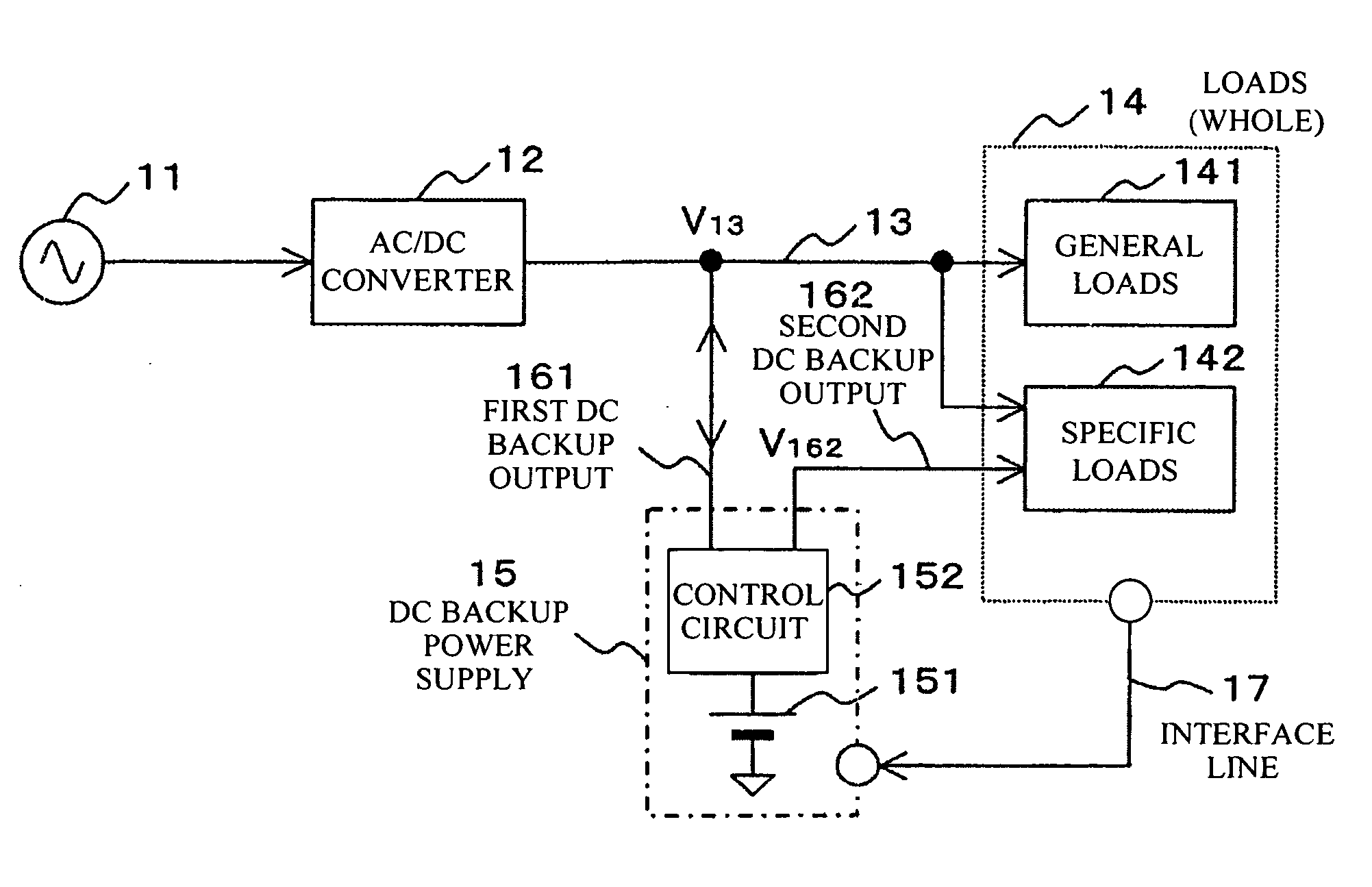
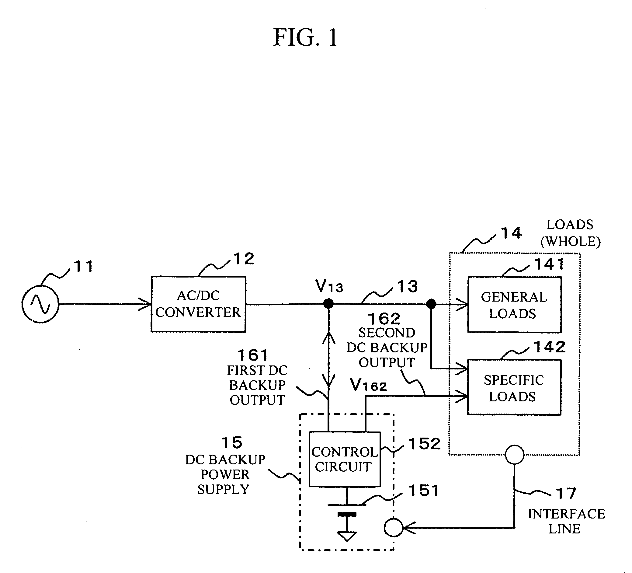
[0027]FIG. 1 is a schematic block diagram of a DC backup power supply system according to the invention. With the present power supply system, an AC at 100 V or 200 V is normally delivered from a commercial AC power source 11 to be converted into DC power by an AC / DC converter 12, and the DC power is supplied to loads 14 through a power line 13. The loads 14 includes a plurality of loads, such as general loads 141, a specific load 142, and so forth, and description is given hereinafter on the assumption that the specific load 142 among the plurality of the loads is a load to which backup is important. A DC backup power supply 15 is installed to provide backup at the time of a power outage of the commercial AC power source 11.

[0028] The DC backup power supply 15 comprises DC power storage means 151, such as a battery, and so forth, and a control circuit 152. The control circuit 152 detects a drop in a voltage V13 of an output power line 13 of the AC / DC converter 12 at the time of the...

second embodiment

[0057]FIG. 7 is a schematic block diagram of a DC backup power supply system according to the invention. The DC backup power supply system according to the present embodiment comprises DC power storage means 151 wherein a multitude of unit batteries 701 to 70n are disposed in a matrix fashion, and connection switchover means 72 for the respective unit batteries arranged in a serial direction are provided. The DC power storage means 151 has a configuration in which respective portions of the unit batteries 701 to 70n, sufficient in capacity to provide backup only, are parallel-connected to an output line 13 of an AC / DC converter 12. A control circuit 152 controls recharging of the respective unit batteries, 701 to 70n, or discharging from the DC power storage means 151 to loads 14, and so forth. For example, the respective unit batteries disposed in the matrix fashion are composed of a single cell or a plurality of battery cells connected in series, and only the respective unit batte...

third embodiment

[0059]FIG. 8 is a schematic block diagram of a disk array provided with a DC backup power supply system according to the invention. With the present embodiment, a power supply system comprising an AC / DC converter 12, a DC backup power supply 15, and so forth is applied to the disk array device. Loads 14 represent the disk array device comprising mainly a disk array control unit 83, and a disk array unit 85. The disk array control unit 83 incorporates a cache memory 81, a CPU 82, and so forth. A plurality of hard disk drives 84 are disposed in the disk array unit 85. Further, the disk array device 14 comprises DC / DC converters 86 to 88, for supplying DC power to individual loads inside the device, and so on. The DC backup power supply 15 has basically the same configuration as that for the embodiment described with reference to FIG. 6, and parts in FIG. 8, corresponding to those in FIG. 6, are denoted by like reference numerals, thereby omitting duplicated description thereof. Furthe...


PUM


Abstract

In the case where there coexist general loads requiring backup only for a short duration and a specific load requiring backup for a longer duration, uninterruptible power with higher reliability is supplied to the specific load with the adoption of a simple configuration. A DC backup power supply system comprises an AC/DC converter for normally supplying DC power to loads in while (the general loads and the specific load, included), and a control circuit for supplying DC output backing up the loads in whole for relatively short time only from a battery at the time of a power outage, while supplying DC output backing up the specific load, such as a cache memory and so forth, for relatively long time. Thus, it is possible to implement an uninterruptible power supply system small in size and low in cost, provided with a function for proper use depending on a prevailing situation.

Description

BACKGROUND OF THE INVENTION [0001] The present invention relates to a DC backup power supply system having a non-service interruption function, and a disk array provided with the same. [0002] With communication / information equipment such as a disk array, AC is received from a commercial AC power source to be thereby converted into DC by an AC / DC converter, whereupon the DC is further adjusted so as to be at various voltages required by respective circuits in the disk array by DC / DC converters before supplying power to the respective circuits (loads). As an uninterrupted power supply (UPS) in this field, there is, for example, a technology disclosed in Patent Document 1. In the case of the technology, a backup power supply is connected to DC paths between a converter and respective loads inside equipment, and power from an AC power source is converted into DC power when the converter is in normal operation, thereby supplying the DC power to the respective loads while charging a batte...

Claims


Application Information

Patent Timeline
Patent Type & Authority Applications(United States)
IPC IPC(8): H02J9/06
CPCH02J9/061
Inventor TAKAHASHI, FUMIKAZUNEMOTO, MINEHIRONEMOTO, ISAOKANOUDA, AKIHIKOHAMAOGI, MASAHIROTAKAHASHI, YOSHIHIDE
Owner HITACHI INFORMATION & TELECOMM ENG LTD
Why Eureka
Try Eureka