Semiconductor chip cooling module with fin-fan-fin configuration

a cooling module and semiconductor chip technology, applied in cooling/ventilation/heating modification, semiconductor device details, semiconductor/solid-state device details, etc., can solve problems such as system errors, rapid overheating phenomenon, and harmful influence on system operation, and achieve the effect of improving the radiating efficiency of heat radiating fins

Inactive Publication Date: 2005-05-12
APACK +1
View PDF10 Cites 39 Cited by
  • Summary
  • Abstract
  • Description
  • Claims
  • Application Information

AI Technical Summary

Benefits of technology

[0019] the bi-directional air intake centrifugal fan in accordance with the second embodiment is capable of timely and artificially improving a radiating efficiency of heat radiating fins by means of a centrifugal fan operated to discharge upward an air entered from an exterior part to an interior part of the both sides of the heat radiating fins.

Problems solved by technology

As described above, since the CPU generates a large quantity of heat during a data processing, when the heat generated from the CPU itself is risen up to a predetermined temperature, the heat affects a harmful influence to a system operation, thereby generating a system error.
However, since the heat radiating apparatus using the prior art heat pipe 32 employs a forced convection method that the heat generated from the CPU 20 is radiated through one row of heat pipe as an intermediate, when the CPU accomplishes a large quantity of calculating function at a time, the CPU 20 generates a rapid overheat phenomenon due to an overload, but the corresponding rapid radiation does not accomplished.
Therefore, in the prior art radiating apparatus, the problem of malfunction of a computer has been often occurred due to an erroneous operation of the CPU having a limitation in counter measure corresponding to a rapid overheat.

Method used


Image

  • Semiconductor chip cooling module with fin-fan-fin configuration
  • Semiconductor chip cooling module with fin-fan-fin configuration
  • Semiconductor chip cooling module with fin-fan-fin configuration

Examples


first embodiment

[0034] the air ventilating means will be described.

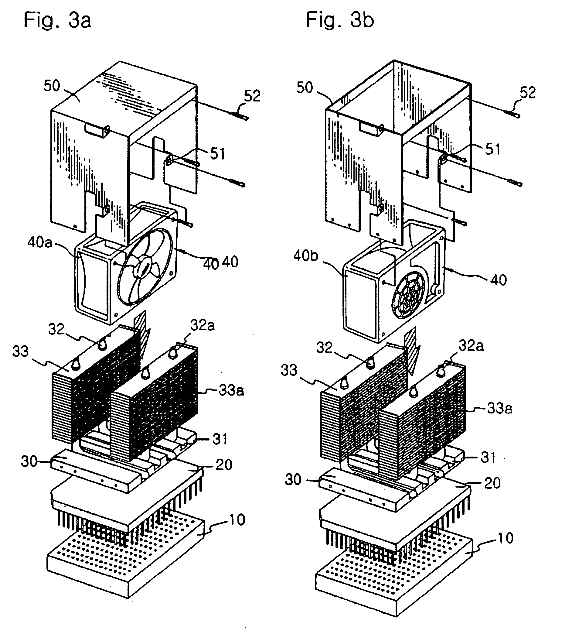
[0035] Referring to FIGS. 3a and 4a, FIG. 3a is an exemplary perspective view of an example employing an axial flow fan as an air ventilating means in accordance with a first embodiment of the present invention, and FIG. 4a is a longitudinal cross-sectional view of the first embodiment shown in FIG. 3a.

[0036] As shown in FIG. 3a, the axial flow fan 40a is installed between the both of heat radiating fins 33 and 33a, and when the axial flow fan 40a is rotated, the air is entered to the one side of the heat radiating fins 33 and discharged to the other side of the heat radiating fins 33a; at this time, the wind passes through between the pair of heat radiating fins 33 and 33a by the axial flow fan 40a to cool the heat of the heat radiating fins 33 and 33a.

second embodiment

[0037] the air ventilating means 40 will be described.

[0038] Referring to FIGS. 3b and 4b, FIG. 3b is an exemplary perspective view of an example employing a bi-directional air intake centrifugal fan as an air ventilating means in accordance with a second embodiment of the present invention; and FIG. 4b is a longitudinal cross-sectional view of the second embodiment shown in FIG. 3b.

[0039] As shown in FIG. 3b, the bi-directional air intake centrifugal fan 40b is installed at a space between the both heat radiating fins 33 and 33a, and the bi-directional air intake centrifugal fan 40b introduce the air to between the both heat radiating fins 33 and 33a to discharge the air upward, thereby cooling the heat radiating fins 33 and 33a by means of the air entered between the heat radiating fins 33 and 33a.

[0040] As described above, a cooling operation of the heat radiating fins 33 and 33a by the air ventilating means 40 located between the plural rows of heat pipes, since a radiating ef...


PUM


Abstract

The present invention relates to a semiconductor chip cooling module with fin-fan-fin configuration employing a heat pipe provided with air ventilating means having a forced convection cooling type radiating method of forcedly cooling heat radiating fins by ventilating a wind to rapidly discharge and cool heat generated from a central processing unit (hereinafter referred to as “CPU”) mounted on a main board of a computer; the present invention comprises a heat radiating plate having a plurality of slots, a pair of heat pipes installed in the slots in a symmetrical relationship, and air ventilating means having a ventilating fan installed between heat radiating pins of the pair of heat pipes, wherein an air is ventilated to the heat radiating pins to forcedly radiate the heat radiating pins. The present invention is capable of embodying a rapid radiation on an overheat of the CPU by employing a forced direct cooling method that air ventilating means is installed at a center of plural rows of heat pipes to ventilate an air to thereby forcedly and directly cool the heat radiating fins mounted on the plural rows of heat pipes.

Description

TECHNICAL FIELD [0001] The present invention relates to a semiconductor chip cooling module with fin-fan-fin configuration employing a heat pipe, and more particularly to a semiconductor chip cooling module with fin-fan-fin configuration employing a heat pipe provided with air ventilating means having a heat radiating function of a forced convection cooling type for forcedly cooling heat radiating fins by ventilating a wind in order to promptly discharge and cool heat generated from a central processing unit (hereinafter referred to as “CPU”) mounted on a main board of a computer. BACKGROUND ART [0002] Generally, as the current society rapidly advances to an information society, a computer capable of calculating (processing) a large quantity of information and data is required; therefore, a CPU capable of rapidly processing a large quantity of data has been developed to satisfy desires of those consumers. [0003] As described above, since the CPU generates a large quantity of heat du...

Claims


Application Information

Patent Timeline
Patent Type & Authority Applications(United States)
IPC IPC(8): H01L23/367H01L23/467H05K7/20
CPCH01L23/3672H01L23/467H01L2924/0002H01L2924/00
Inventor SONG, KYU SOP
Owner APACK
Why Eureka
Try Eureka