Computed tomography with z-axis scanning

Inactive Publication Date: 2005-05-12
GE MEDICAL SYST GLOBAL TECH CO LLC +1
View PDF21 Cites 60 Cited by
  • Summary
  • Abstract
  • Description
  • Claims
  • Application Information

AI Technical Summary

Benefits of technology

[0016] Another object of the invention is to acquire x-ray attenuation data of the entire heart during a gated cardiac scan. The electronic scan along the

Problems solved by technology

Reconstructions using too few projections or a limited number of gantry angles may produce images with “artifacts”, typically streaks, that mar the tomographic image.
The time required to collect projection data over a volume using conventional fan-beam tomography can be substantial and may preclude the use of tomography in situations where large volumes are to be monitored in real-time (for example, in dynamic contrast enhanced studies) or where there is unavoidable patient or organ motion during the acquisition time (for example, cardiac studies).
This a

Method used


Image

  • Computed tomography with z-axis scanning
  • Computed tomography with z-axis scanning
  • Computed tomography with z-axis scanning

Examples


Embodiment Construction

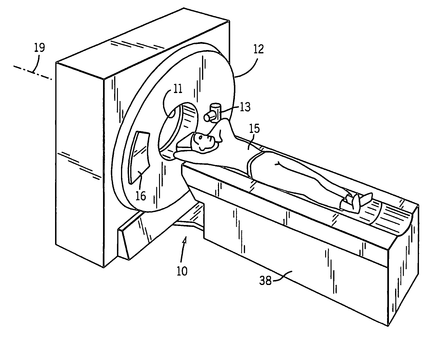
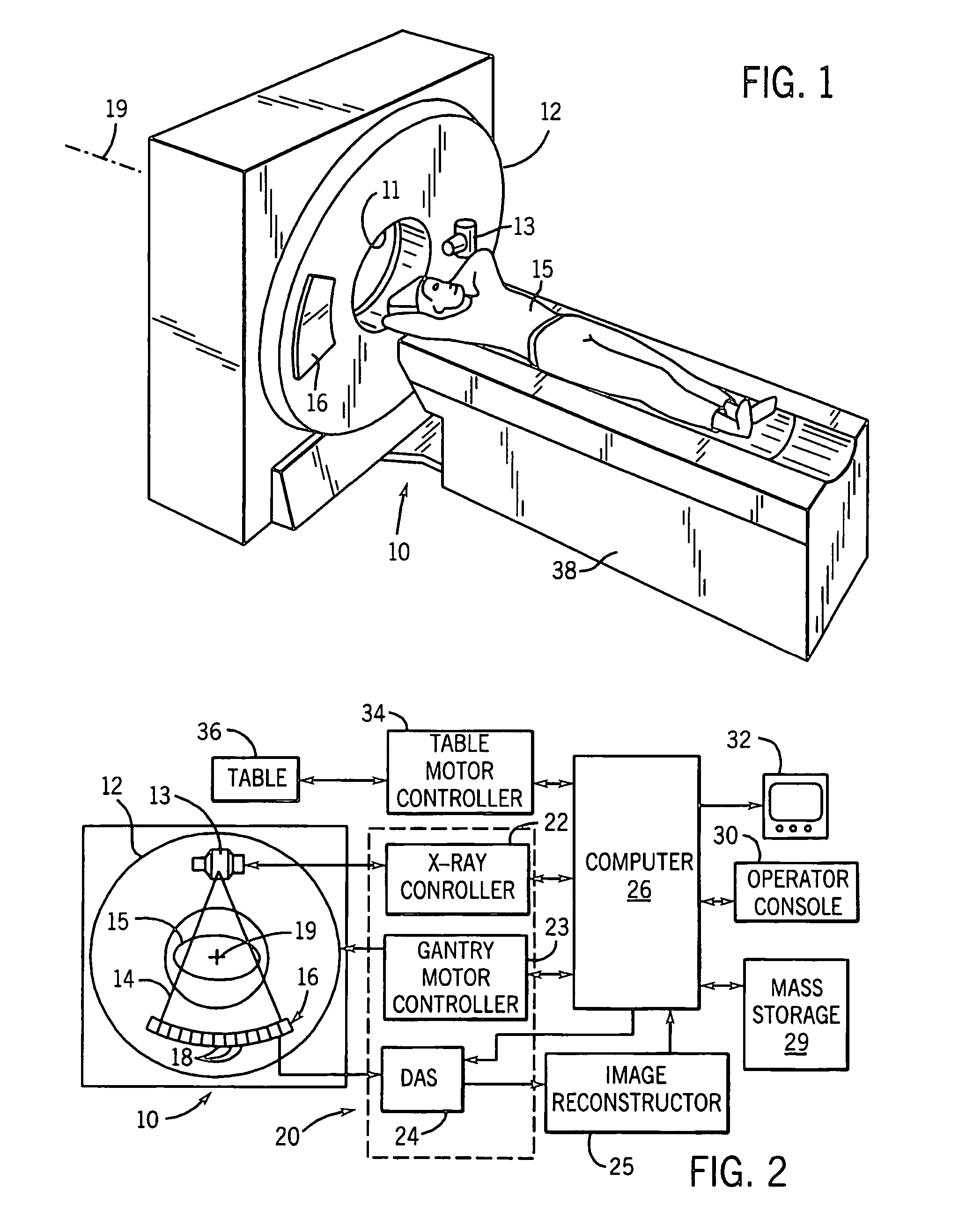
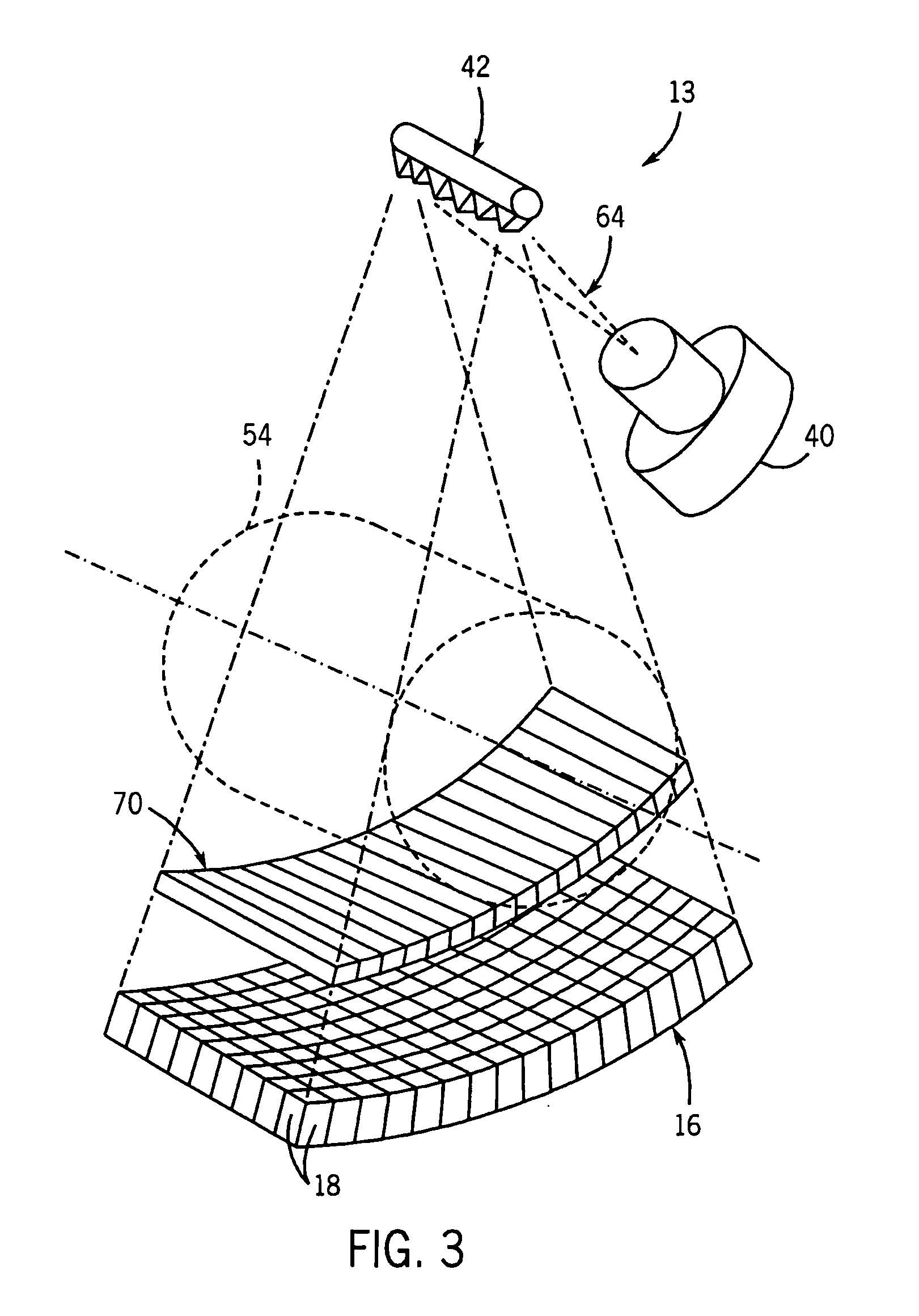
[0028] With initial reference to FIGS. 1 and 2, a computed tomography (CT) imaging system 10 includes a gantry 12 representative of a “third generation” CT scanner. Gantry 12 has an x-ray source 13 that projects a cone beam of x-rays 14 toward a detector array 16 on the opposite side of the gantry. The detector array 16 is formed by a number of detector elements 18 which together sense the projected x-rays that pass through a medical patient 15. Each detector element 18 produces an electrical signal that represents the intensity of an impinging x-ray beam and hence the attenuation of the beam as it passes through the patient. During a scan to acquire x-ray projection data, the gantry 12 and the components mounted thereon rotate about a center of rotation, or z-axis 19.

[0029] The rotation of the gantry and the operation of the x-ray source 13 are governed by a control mechanism 20 of the CT system. The control mechanism 20 includes an x-ray controller 22 that provides power and timi...


PUM


Abstract

A CT imaging system includes a two-dimensional detector array and an x-ray source that both revolve around the subject during a scan. The x-ray source produces a cone beam of x-rays and the focal point of this cone beam is electrically moved to different locations along the z-axis to increase the z-axis extent of the ROI that can be imaged without patient table movement. Different focal point scan patterns are described for a variety of different clinical applications.

Description

CROSS-REFERENCE TO RELATED APPLICATIONS [0001] This application claims the benefit of U.S. Provisional patent application Ser. No. 60 / 518,530 filed on Nov. 7, 2003 and entitled “Computed Tomography With Z-Axis Scanning”.STATEMENT REGARDING FEDERALLY SPONSORED RESEARCH OR DEVELOPMENT [0002] This invention was made with United States government support awarded by the following agencies: NIH HL62425. The United States has certain rights in this invention.BACKGROUND OF THE INVENTION [0003] The present invention relates to x-ray computed tomography (CT) and specifically to a CT system and method providing high-speed data acquisition. [0004] Conventional x-ray computed tomography may employ an x-ray source collimated to produce a narrow fan-shaped beam directed along the transverse plane through a patient to be received by linear multi-element detector array. [0005] The x-ray source and detector array may be mounted on a gantry to be rotated about a patient to obtain “projections” measuri...

Claims


Application Information

Patent Timeline
IPC IPC(8): A61B6/00A61B6/03
CPCA61B6/032A61B6/4028A61B6/4291A61B6/541A61B6/027A61B6/4085
Inventor MISTRETTA, CHARLES A.PATCH, SARAHBOUTCHKO, ROSTYSLAVHSIEH, JIANG
Owner GE MEDICAL SYST GLOBAL TECH CO LLC
Why Eureka
Try Eureka