Light-amount control device for photographing

Inactive Publication Date: 2005-05-12
PENTAX RICOH IMAGING CO LTD
View PDF3 Cites 4 Cited by
  • Summary
  • Abstract
  • Description
  • Claims
  • Application Information

AI Technical Summary

Benefits of technology

[0012] A camera system according to the present invention, includes a lens barrel and a light-amount control device body to which the lens barrel is detachably attached. The lens barrel includes a photographing optical system and a peripheral light amount data memory that memorizes peripheral light amount data. The light-amount control device body includes a plurality of lighting units and a lighting unit controller. Each of the plurality of lighting units emits light for illuminating a photographing area of the photographing optical system. The lighting unit controller controls the lighting units so that the intensity of light at a wider i

Problems solved by technology

However, because a single LED can not emit enough light for photographing,

Method used


Image

  • Light-amount control device for photographing
  • Light-amount control device for photographing
  • Light-amount control device for photographing

Examples


first embodiment

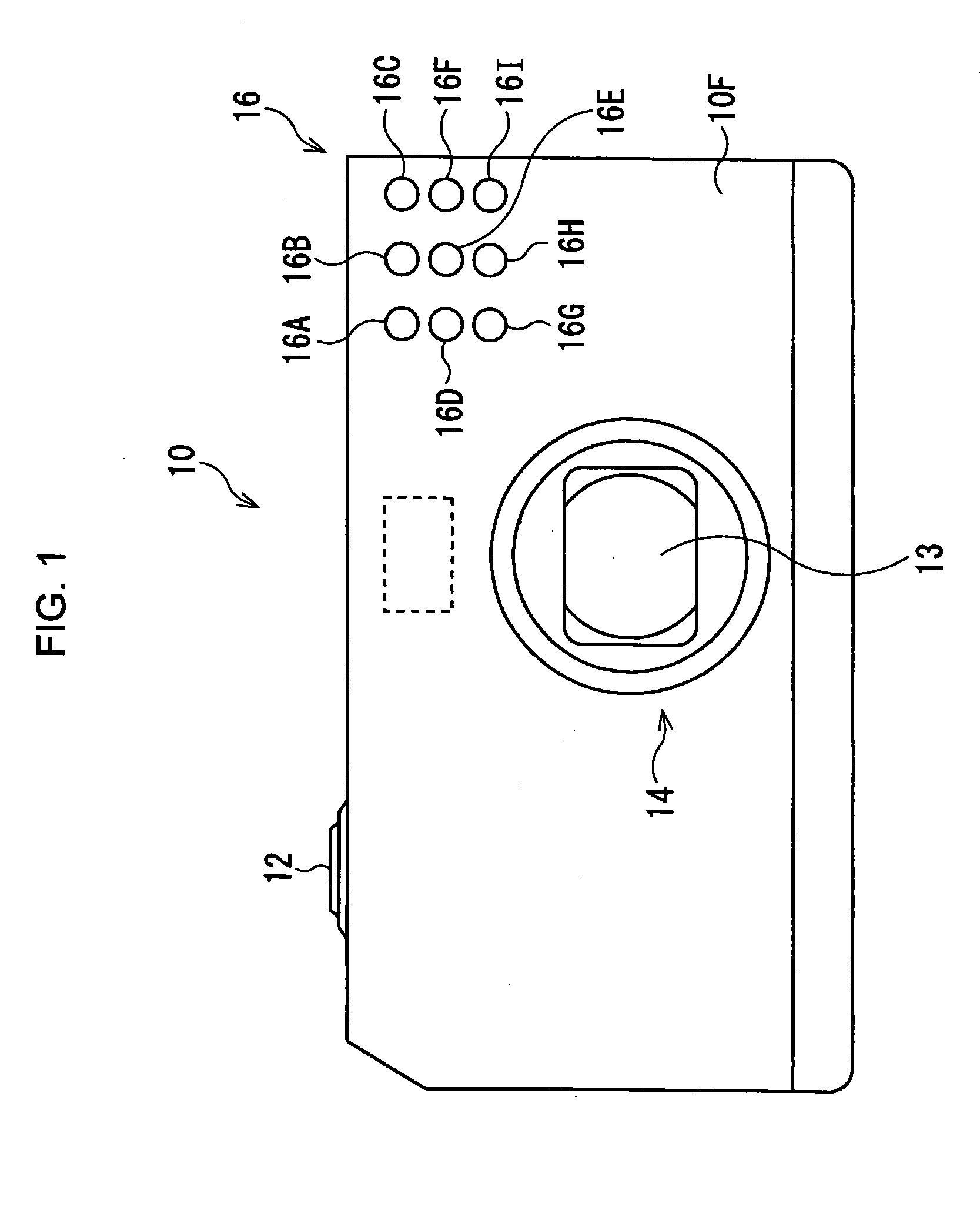
[0023]FIG. 1 is a front view of a digital camera of the present invention.

[0024] A digital camera 10 has a release button 12, a lens barrel 14 including a photographing lens 13, and a lighting apparatus 16. The lighting apparatus 16 includes first to ninth lighting units 16A-16I, having an LED respectively as a light source. The first to ninth lighting units 16A-16I are buried in the front surface 10F of the digital camera 10 in a matrix manner of 3 rows and 3 columns. A fifth lighting unit 16E located in the center of all the lighting units 16A-16I, emits light in a parallel direction to the optical axis of the lens barrel 14 at predetermined illuminating angles. Other lighting units also emit light that defuses, and then the entire photographing area of the digital camera 10 is illuminated. For example, a first lighting unit 16A, emits light towards the upper right direction from a user. Here, the ratio of width in the horizontal direction to length in the vertical direction of th...

second embodiment

[0048] In a digital camera 10 of the second embodiment, a photographing lens 13 is detachably attached to a digital camera body 50 of the digital camera 10. The lens barrel 14 has a lens side interface 35 for connection to the camera body 50. On the other hand, the camera body 50 has a camera side interface 33, and then, the lens side interface 35 and the camera side interface 33 are connected to each other when the lens barrel 14 and the camera body 50 are connected to each other.

[0049] The lens barrel 14 also has a lens side lens driving mechanism 31 for driving the photographing lens 13. The lens side lens driving mechanism 31 and a camera side lens driving mechanism 37 provided in the camera body 50, are engaged with each other when the lens barrel 14 is attached to the camera body 50. These lens driving mechanisms are controlled by an AF motor 29 to drive the photographing lens 13 for adjusting its focus.

[0050] The lens barrel 14 includes a ROM 27 in which the data of the phot...


PUM


Abstract

A light-amount control device includes a plurality of lighting units each of which emits light for illuminating a photographing area of a photographing optical system. Further, the light-amount control device includes a peripheral light amount data calculator and a lighting unit controller. The peripheral light amount data calculator calculates a peripheral light amount data defining ratios of light emission intensities for the lighting units, to make the illuminance of an image plane of a standard object that has a flat surface being perpendicular to the optical axis of the photographing optical system and having a constant reflecting light ratio, constant when the standard object is illuminated by the lighting units. The image plane is formed by reflected light from the surface of the standard object that enters the photographing optical system. The lighting unit controller controls the lighting units so that the intensity of light at a wider illuminating angle to an optical axis of the photographing optical system becomes higher, based on the peripheral light amount data.

Description

BACKGROUND OF THE INVENTION [0001] 1. Field of the Invention [0002] The present invention relates to a light-amount control device for controlling the amount of light emitted towards subjects to be photographed by silver-halide film cameras, digital cameras, cellular phones, and other devices with photographing functions. [0003] 2. Description of the Related Art [0004] Recently, a smaller amount of light than before is required for illuminating objects, with a lighting apparatus, because of improvements in sensitivity of silver-halide films, color films, and CCDs. Therefore, even though the amount of light output by LEDs is smaller than that output by conventional xenon tubes, usage of LEDs as a lighting apparatus for photographing is proposed for improved lighting efficiency, reduced power consumption, and increased life. [0005] However, because a single LED can not emit enough light for photographing, an apparatus including a plurality of LEDs as light sources, is proposed. [0006]...

Claims


Application Information

Patent Timeline
IPC IPC(8): G03B15/03G03B15/02G03B15/05
CPCG03B15/03H04N2101/00H04N5/2354H04N5/23296H04N23/69H04N23/74
Inventor SEO, SHUZOKAKIUCHI, SHINICHI
Owner PENTAX RICOH IMAGING CO LTD
Why Eureka
Try Eureka