
Ultrasound treatment and imaging system

a technology of ultrasonic equipment and imaging system, which is applied in the field of ultrasonic equipment, can solve the problems of irregular elevation and depression of the dermis, affecting the function of the body, so as to reduce or prevent cellulite, enhance and improve the effect of the integrity of the connective tissue layer

Inactive Publication Date: 2005-05-12
COSTANTINO PETER
View PDF4 Cites 77 Cited by
  • Summary
  • Abstract
  • Description
  • Claims
  • Application Information

AI Technical Summary

Problems solved by technology

The distribution of adipose tissue throughout the body is not uniform.
This deficiency allows depot fat below the interface to protrude up through the fibrous layer and into the dermis, thereby causing irregular elevations and depressions of the dermis characterized by a “dimpled” appearance.
That is, the method of Knowlton does not stimulate production of collagen by cells within the target tissue.
While Knowlton '753 does not present data specifying a temperature threshold above which the objectives of the method are achieved, the thermoregulating ability of the body renders it difficult, if not impossible, to raise the temperature of a layer of tissue underlying the cooled epidermis to a point where denaturation of collagen will occur by employing non-invasive hyperthermia means.

Method used


Image

  • Ultrasound treatment and imaging system
  • Ultrasound treatment and imaging system
  • Ultrasound treatment and imaging system

Examples


Embodiment Construction

[0045] In accordance with the present invention, the elastic layer of connective areolar tissue overlying the depot fat, at the interface of the adipose cell layer and the dermis, is damaged to stimulate the introduction of fibroblasts and the formation of a more dense layer of connective tissue which defines smaller interstices and thus is more effective to maintain the depot fat below the interface, as compared to the condition in patients suffering from cellulite, where the depot fat is protruding out from the elastic layer and accumulate directly under the dermis, forming globules of adipose tissue which are visible as small lumps under the skin.

[0046] The controlled and focused application of traumatic ultrasonic waves to cells comprising a thin layer of tissue adjacent to and including the interface between the dermis and subcutaneous adipose tissue results in tissue destruction followed by an inflammatory response accompanied by the migration of fibroblasts into the area. Th...


PUM


Abstract

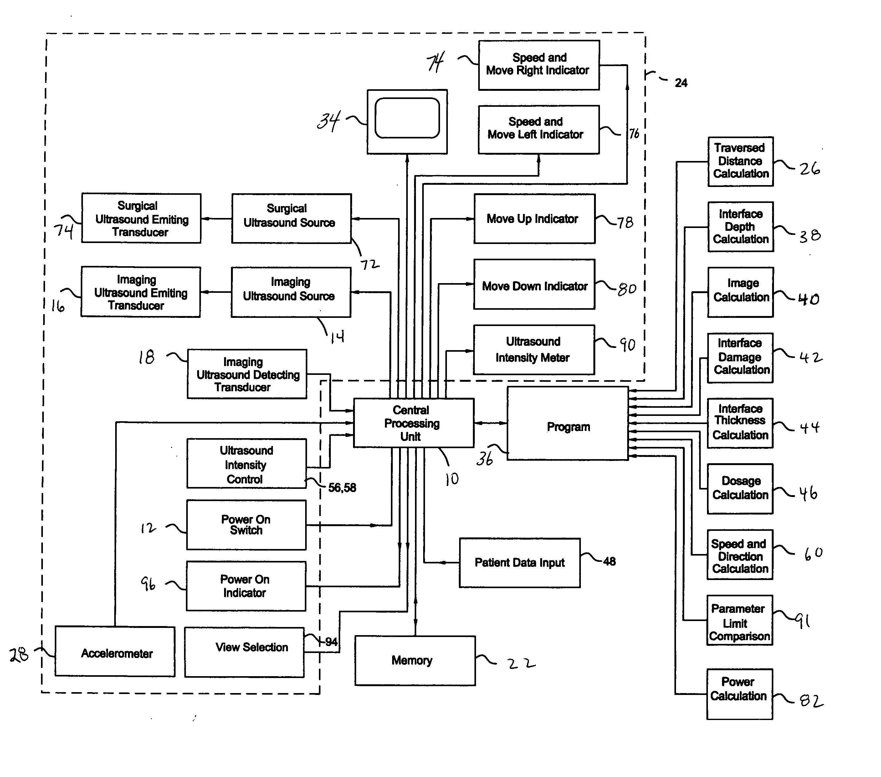
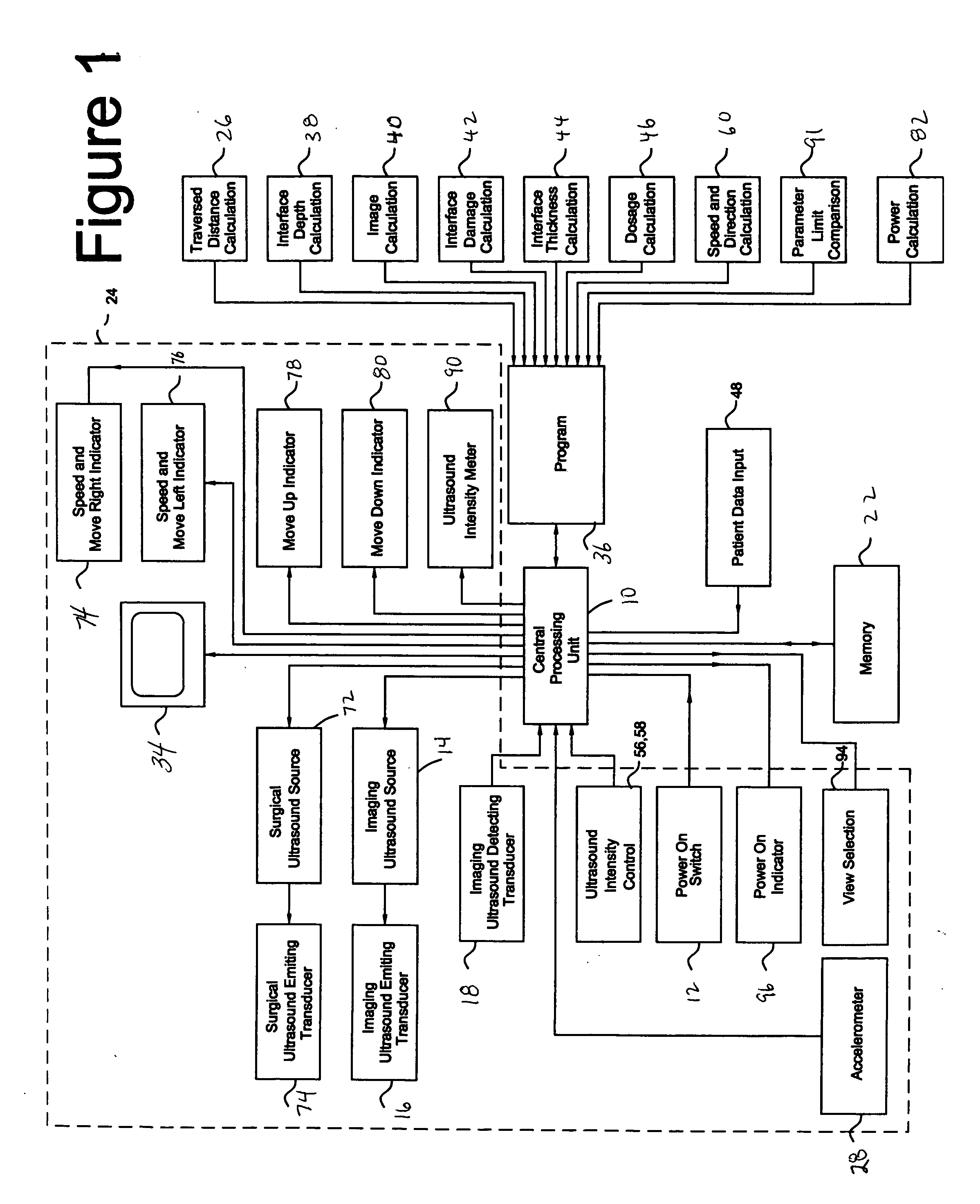
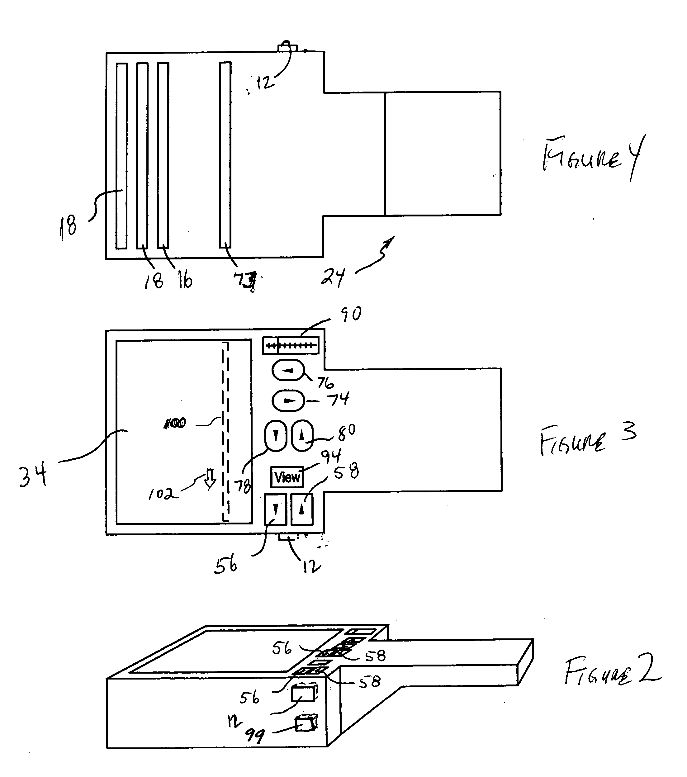
Apparatus for treating cellulite under the surface of the skin comprising a surgical ultrasonic energy source is disclosed. An ultrasonic energy transmitting surface is driven by a surgical ultrasonic energy source. The ultrasonic energy transmitting surface is configured to concentrate ultrasonic energy in the layer of connective tissue lying at the interface between the dermis and the subcutaneous adipose tissue. The surgical ultrasonic energy source is of sufficient power to cause disruption of the layer of connective tissue lying at the interface between the dermis and the subcutaneous adipose tissue during a dosage period. An imaging ultrasonic energy transmitting surface is driven by the imaging ultrasonic energy source. An imaging ultrasonic energy detector is coupled to receive the reflected output of the imaging ultrasonic energy transmitting surface. A computing device is coupled to the output of the imaging ultrasonic energy detector. A program resident in the computing device configures the computing device to generate an image of tissues under the surface of the skin of a patient. A display for displaying the image of tissues under the surface of the skin of the patient provides the person implementing the treatment with first and second images. The first image is a before ultrasound treatment three dimensional or other image and the second image is an after ultrasound treatment image of the tissue is treated. An applicator housing is configured to be held by the hand of an individual, the imaging ultrasonic energy detector is mounted on the applicator housing.

Description

CROSS REFERENCE TO RELATED APPLICATIONS [0001] This application claims the benefit of U.S. provisional patent application No. 60 / 491,601, filed Jul. 31, 2003, (Attorney Docket No. PDC019) the entire disclosure of which is hereby incorporated herein by reference thereto.STATEMENT REGARDING FEDERALLY SPONSORED RESEARCH OR DEVELOPMENT [0002] Not Applicable. BACKGROUND OF THE INVENTION [0003] 1. Field of the Invention [0004] The invention relates both to 1) an ultrasonic apparatus for treating patients suffering from cellulite, (a condition characterized by portions of subdermal adipose fat-containing tissue migrating into and through the subdermal elastic tissue matrix) and for the purpose of causing the contraction of laxed or wrinkled tissues below the surface of the epidermis, and also to 2) a method using ultrasonic energy to non-invasively generate a relatively robust connective tissue matrix at the interface of the dermis and the adipose tissue. [0005] 2. Prior Art [0006] The dis...

Claims


Application Information

Patent Timeline
Patent Type & Authority Applications(United States)
IPC IPC(8): A61B5/05A61B8/08A61B19/00A61F2/00A61F7/00A61F7/12A61NA61N7/02
CPCA61B8/0858A61B8/4472A61N2007/0008A61B2019/5276A61N7/02A61B8/463A61B2090/378
Inventor COSTANTINO, PETER
Owner COSTANTINO PETER
Learn More