
Cheek path airway and cheek pouch anchor

Active Publication Date: 2005-05-19
WEDEMEYER LOWELL R
View PDF11 Cites 58 Cited by
  • Summary
  • Abstract
  • Description
  • Claims
  • Application Information

AI Technical Summary

Benefits of technology

[0022] The cheek path airway bypasses nasal airways and provides oral air flow supplemental to nasal flow, even though the user's lips, teeth and jaws are otherwise closed. Thus, the cheek path airway can provide supplemental air volumes to mitigate breathing impairment caused by restriction of a user's nasal airways without a user having to switch to open-mouth breathing.
[0081] Examples of existing intra-oral, jaw-control and tongue-control devices with which it is conceived the invention might be used in combination (perhaps requiring some modification) are: Fenton, U.S. Pat. No. 5,499,633; Halstrom, U.S. Pat. No. 5,868,138; Strong, U.S. Pat. No. 6,418,933; Thornton, U.S. Pat. No. 6,325,064 B1; Meade, U.S. Pat. No. 6,055,986; Belfer, U.S. Pat. No. 6,092,523; Frantz, U.S. Pat. No. 6,109,625; Bergersen, U.S. Pat. No. 6,129,084; Thornton, U.S. Pat. No. 6,155,262; David, U.S. Pat. No. 6,450,167 B1; Tielmans, U.S. Pub. No. 2001, 0027793 A1 and U.S. Pat. No. 6,408,852 B2; Gaskell, U.S. Pub. No. 2002 / 0000230 A1; and Dort, Pub. No. US 2002 / 0117178 A1 (August 2002). See also Thornton, U.S. Pat. No. 6,209,542 (nasal mask combined with dental device). Wagner, U.S. Pat. No. 5,566,684 (1996) discloses a mouthguard which a user can self-fit to the user's maxillary dentition to mitigate nocturnal teeth grinding. An embodiment of Wagner's device, with instructions for self-fitting by users, is marketed under the trade name “The Doctor's Night Guard”, by Dental Concepts, Paramus, N.J., USA. There are advantages where a cheek-path airway is physically separated from the jaw-control and tongue-control devices, but designed to be used in a user's mouth in combination with such devices. The cheek-path airway then can be inserted or removed separately from the jaw- or tongue-control device, enabling separate handling of the cheek-path airway and such devices, such as separate fitting, adjustment, cleaning, and replacement. Moreover, it is conceived that existing jaw- and tongue-control devices which do include built-in airways could be simplified, and thus more readily constructed, if such built-in airways are deleted and their function replaced by a physically separate cheek-path airway adapted for combination use with such modified devices.

Problems solved by technology

Closed-mouth, nasal breathing through restricted nasal air ways reduces ventilation volume and can impair breathing and sleep.
Scientific and medical experts have reported (or hypothesized) a variety of contributing and causal factors other than nasal airway restriction for hypopnea and apnea, such as sagging of the base of the tongue, and possibly the lower jaw, towards the throat, resulting in restriction or blockage of the throat air way.
Nelson's devices are designed for stand-alone cheek-side positioning; that is, they are not anchored to teeth-engaging or palate-engaging dental devices.
Nelson does not disclose any structure curving around a user's rear-tooth corner, or passing into or through a user's rear-jaw gap, or extending from the user's rear-jaw gap over the user's tongue into airspace in a user's rear-mouth cavity.

Method used


Image

  • Cheek path airway and cheek pouch anchor
  • Cheek path airway and cheek pouch anchor
  • Cheek path airway and cheek pouch anchor

Examples


Embodiment Construction

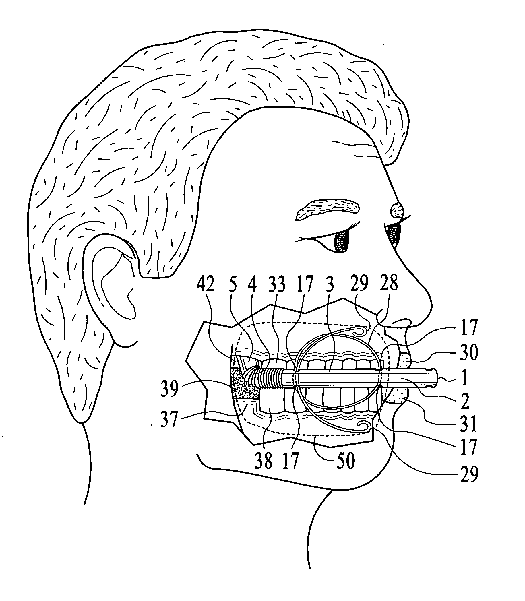
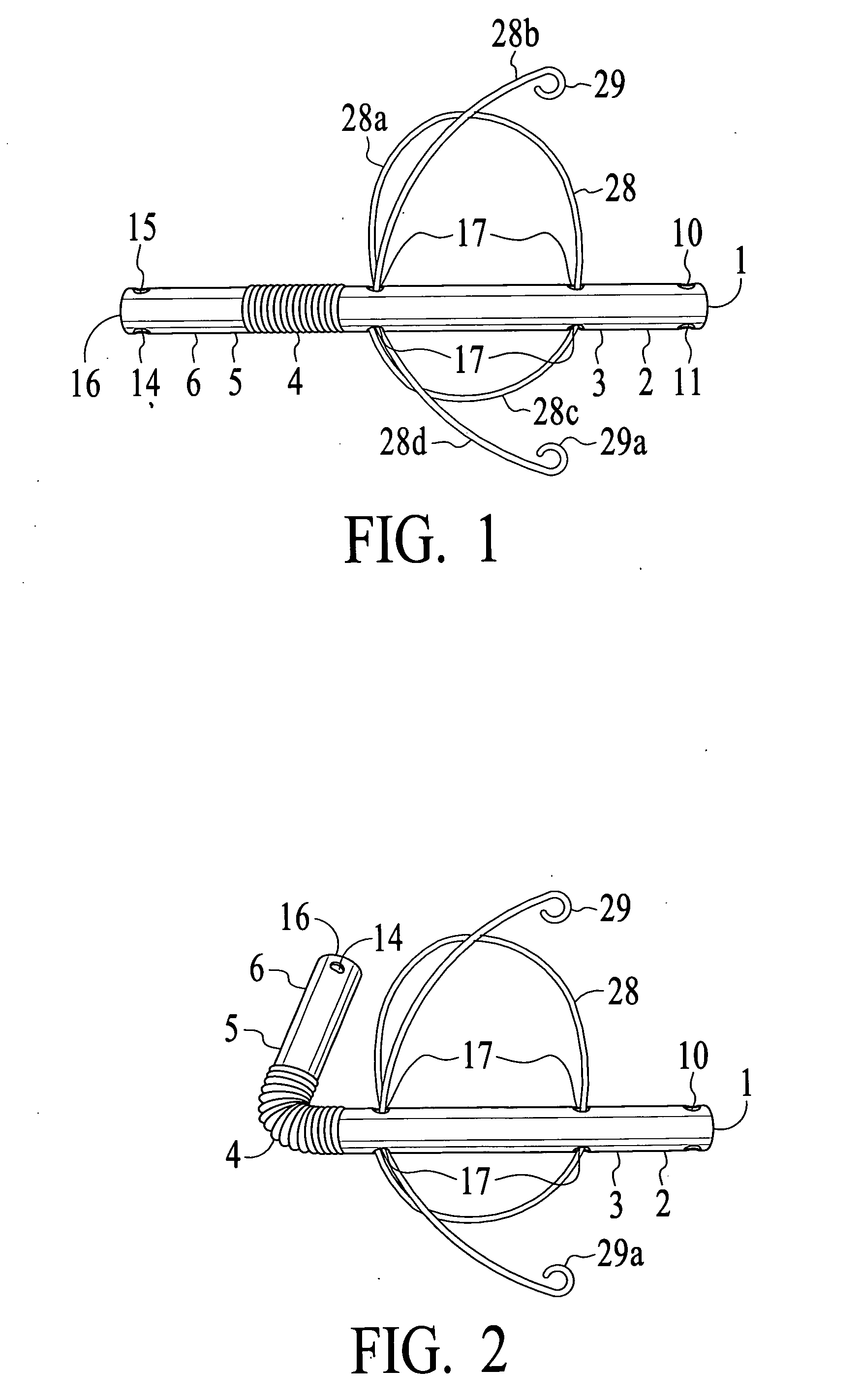
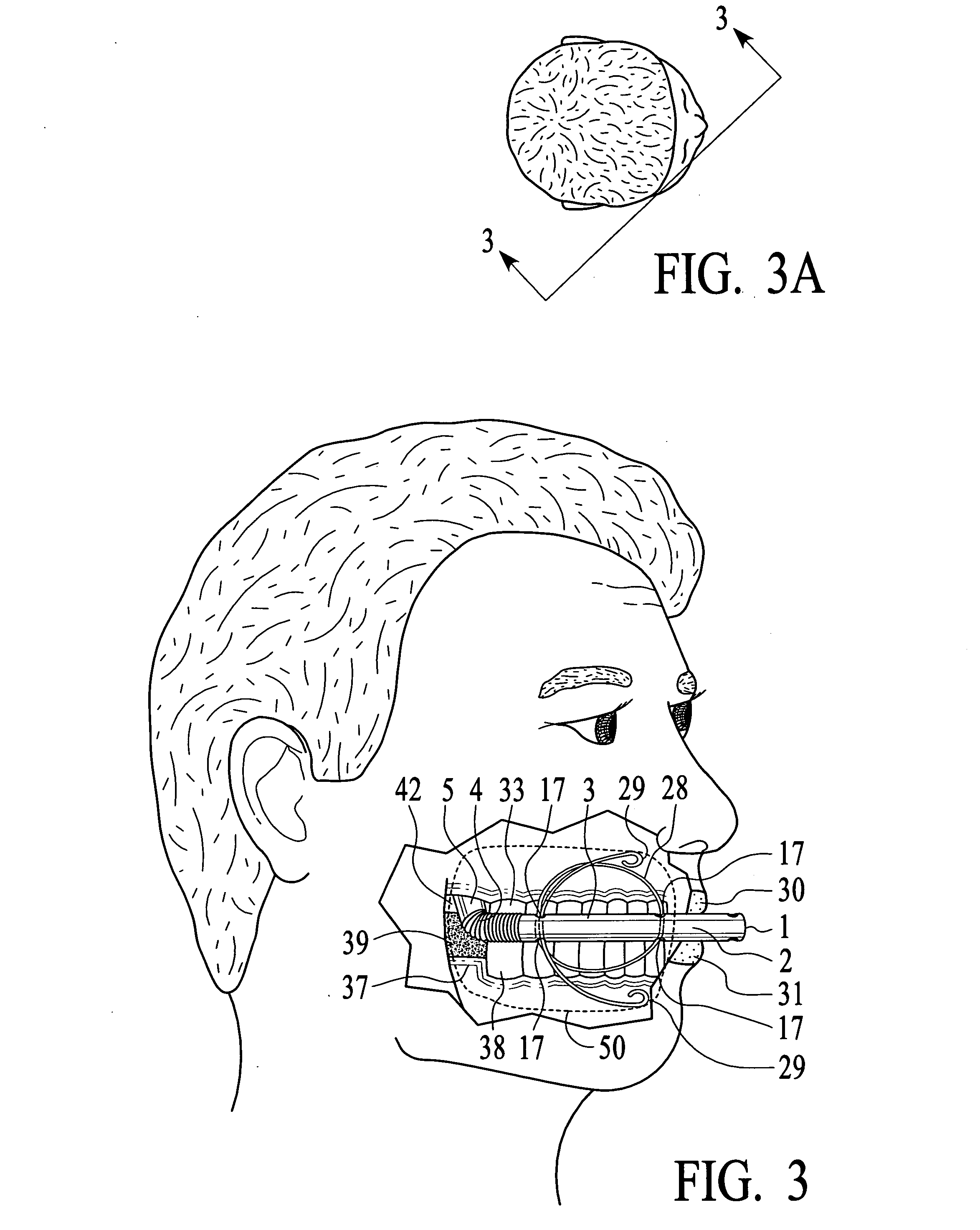
[0198] Airway Tube. In a preferred version, the cheek path airway is formed as a relatively rigid tube with flexible joints interspersed at strategic positions along the tube's longitudinal axis. The more rigid sections of the tube provide structural stability and better leverage to avoid the biting surfaces of a user's teeth, as well as to better project the internal and external open ends of the airway into desirable locations. By reference to FIGS. 3, 4, and 15, the user's inner cheek wall (labeled 32 in FIG. 4, not shown in FIGS. 3 and 15), drapes over and provides cheek-side pressure upon cheek-side portion 3 which is relatively rigid along the longitudinal axis. By reference to FIG. 15 the draping effect of the user's cheek (not shown) urges cheek-side portion 3 against sleeve 53 and arm 54 of the strut of the dental device, constraining rear-tooth corner portion 4 and rear-jaw gap portion 5 of the tube from yawing into the inter occlusal space between mandibular portion 52 an...


PUM


Abstract

An airway is adapted to lie in a cheek pathway in a user's mouth, traversing a path from a position outside a user's lips, between a user's otherwise closed lips, along a user's inner cheek wall outside a user's dental arches, curving dorsally of a user's rear-most teeth through a user's rear-jaw space, and reaching into airspace over a user's tongue in a user's rear-mouth cavity. The airway provides supplemental air to a user's rear-mouth cavity independently of a user's restricted nasal airways while a user's lips remain closed. The airway is adapted to be manufactured in-line and folded by a user to fit a particular user's cheek pathway. There are single-cheek and dual-cheek versions. Extensions of the airway can anchor it about a user's lips or ears. A cheek pocket anchor, formed of a resilient filament, is adapted for placement adjacent to a user's inner cheek wall within a user's cheek pocket and is user-adjustable to fit a particular user's cheek pocket. Spring-like action of the cheek pocket anchor dynamically maintains a bridge spanning across a user's inter occlusal space and lip opening as a user's jaws open and close. The cheek pocket anchor can be formed of a series of connected loops, the spans of which can be mutually adjusted to enable adjustment of the span of the whole cheek pocket anchor. The cheek pocket anchor is adapted to be joined to a work piece, such as a cheek path airway, to stabilize that work piece in a user's mouth. The cheek path airway, with or without the cheek pocket anchor, is adapted for use in combination with mandibular jaw-control and tongue-control devices which restrain a user's mandible and tongue from sagging into a user's throat airway, whereby the combination of airway and such jaw and tongue control devices simultaneously mitigates restrictions in a user's nasal and throat airways.

Description

RELATED APPLICATIONS [0001] There are no related applications. STATEMENT REGARDING FEDERALLY SPONSORED RESEARCH OR DEVELOPMENT [0002] No federally-sponsored research and development is involved. BACKGROUND OF THE INVENTION. [0003] 1. Field of the Invention [0004] The field of the invention is oral conduits for fluids, including oral airways. [0005] 2. Description of Related Art [0006] Nasal Breathing Restrictions. [0007] Some persons at times breathe nasally during sleep, with the lips and jaws closed, thereby eliminating the mouth as an effective airway. Closed-mouth, nasal breathing through restricted nasal air ways reduces ventilation volume and can impair breathing and sleep. [0008] Restrictions in the nasal airway path may significantly contribute to breathing insufficiency during sleep in some persons who breathe nasally with lips closed. Scientific and medical experts have reported (or hypothesized) a variety of contributing and causal factors other than nasal airway restrict...

Claims


Application Information

Patent Timeline
IPC IPC(8): A61F5/56A61M16/04
CPCA61F5/566A61M16/10A61M2210/0637A61M16/00A61M16/0493A61C3/00A61C7/36A61B17/02A61B19/00A61B19/22A61C7/10A61C3/04A61F5/37A61B19/26A61B19/24A61C7/00A61F5/3707A61M2210/0631A61B34/70A61B90/50A61B90/02A61B90/00
Inventor WEDEMEYER, LOWELL R.
Owner WEDEMEYER LOWELL R
Learn More