Heat exchanger

a heat exchanger and heat exchange technology, applied in the field of heat exchangers, can solve the problems of increasing so as to achieve the effect of increasing the heat exchange efficiency of the heat exchanger, reducing the number of assembly steps, and ensuring the heat exchange efficiency

Inactive Publication Date: 2005-05-19
HONDA MOTOR CO LTD
View PDF13 Cites 9 Cited by
  • Summary
  • Abstract
  • Description
  • Claims
  • Application Information

AI Technical Summary

Benefits of technology

[0007] The present invention has been achieved under the above-mentioned circumstances, and it is a first object thereof to maximize the heat exchange efficiency of a heat exchanger. Furthermore, it is a second object of the present invention to ensure sufficient rigidity while lightening the weight by reducing the thickness of a casing of a heat exchanger.

Problems solved by technology

However, in the arrangement described in Japanese Patent Application Laid-open No. 2001-207839, in order to increase the heat transfer area density on the downstream side of the exhaust gas passage, it is necessary to mount a large number of spirally wound pipe members therein with high density, thus not only increasing the number of joints of the pipe members and thereby increasing the number of assembly steps, but also since the flow rate of water flowing through the pipe members easily varies from member to member, there is the possibility that the heat exchange efficiency might deteriorate or the pipe members might be heated while empty.
Since the heat transfer member contributes only to an improvement of the rigidity of the dividing wall and cannot contribute to an improvement of the rigidity of the casing, it is therefore necessary to increase the thickness of the casing in order to ensure a required strength, and there is thus the problem of an increase in the weight of the casing.
Furthermore, in the above-mentioned arrangement described in Japanese Patent Application Laid-open No. 6-300207, since it is necessary to reduce the cross-sectional area on the downstream side of the passage through which the combustion gas flows, the overall shape of the boiler is greatly restricted, thus causing the problem that the degrees of freedom in the design are reduced.

Method used


Image

  • Heat exchanger
  • Heat exchanger
  • Heat exchanger

Examples


Embodiment Construction

[0046] One embodiment of the present invention is explained below with reference to the attached drawings.

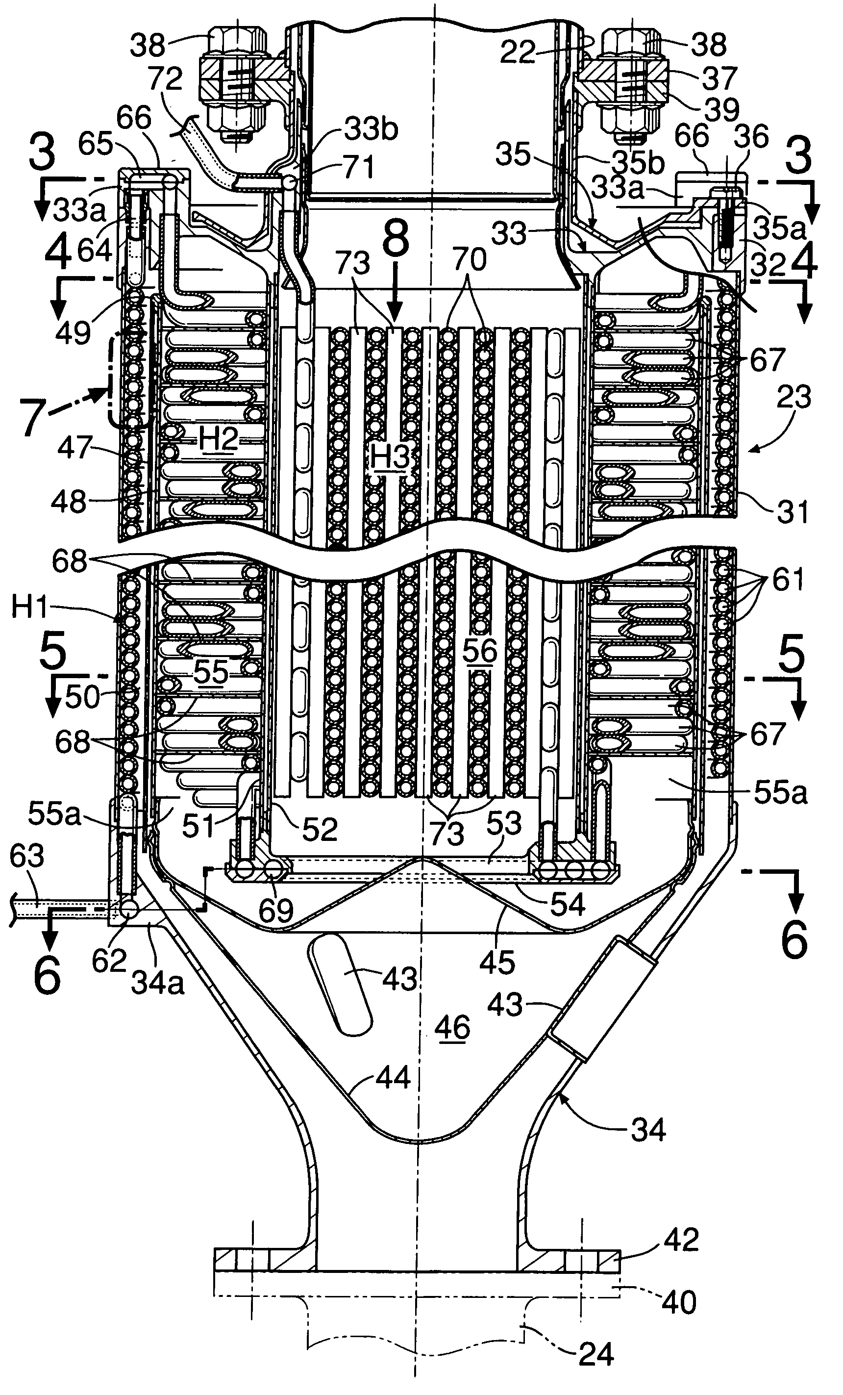
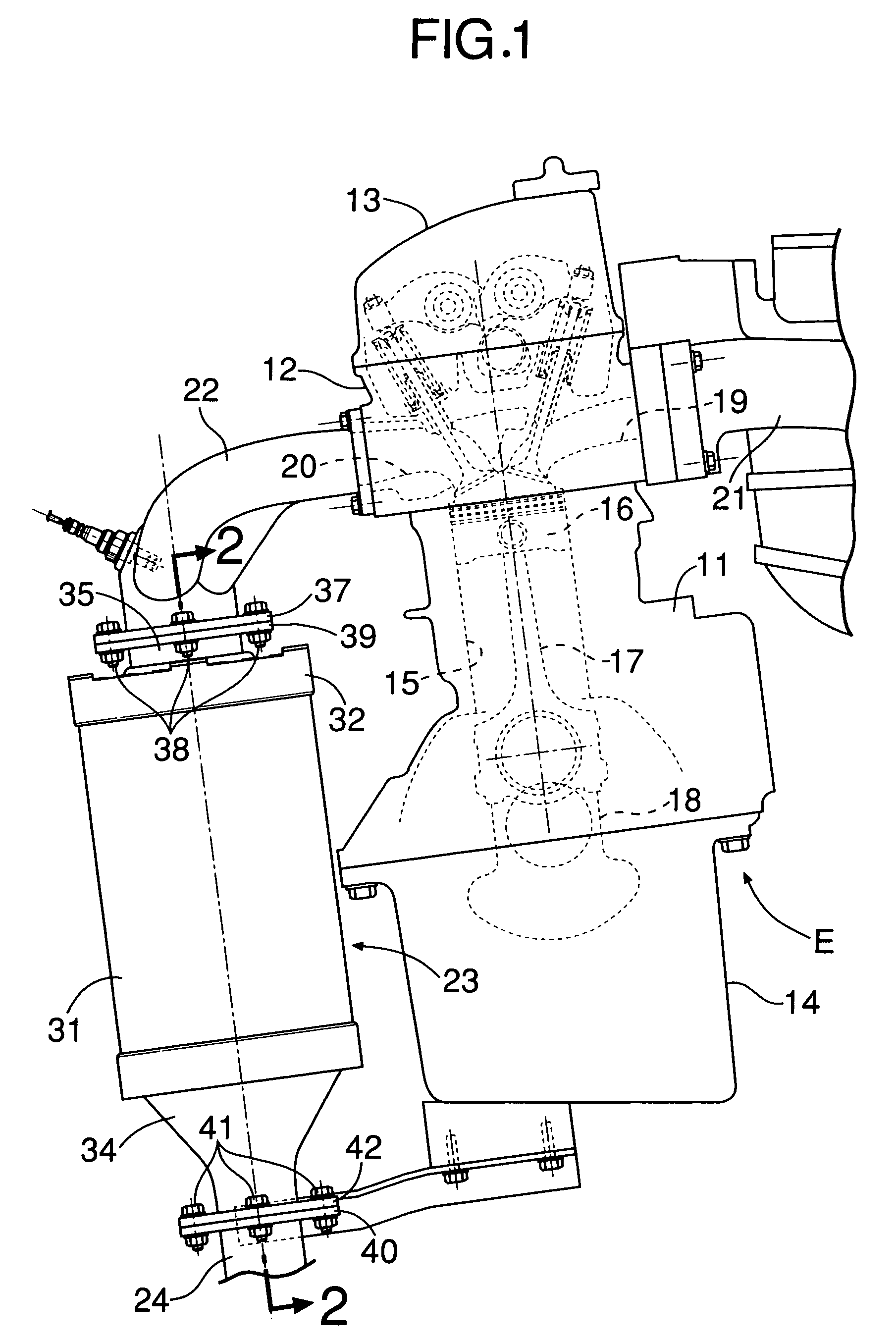
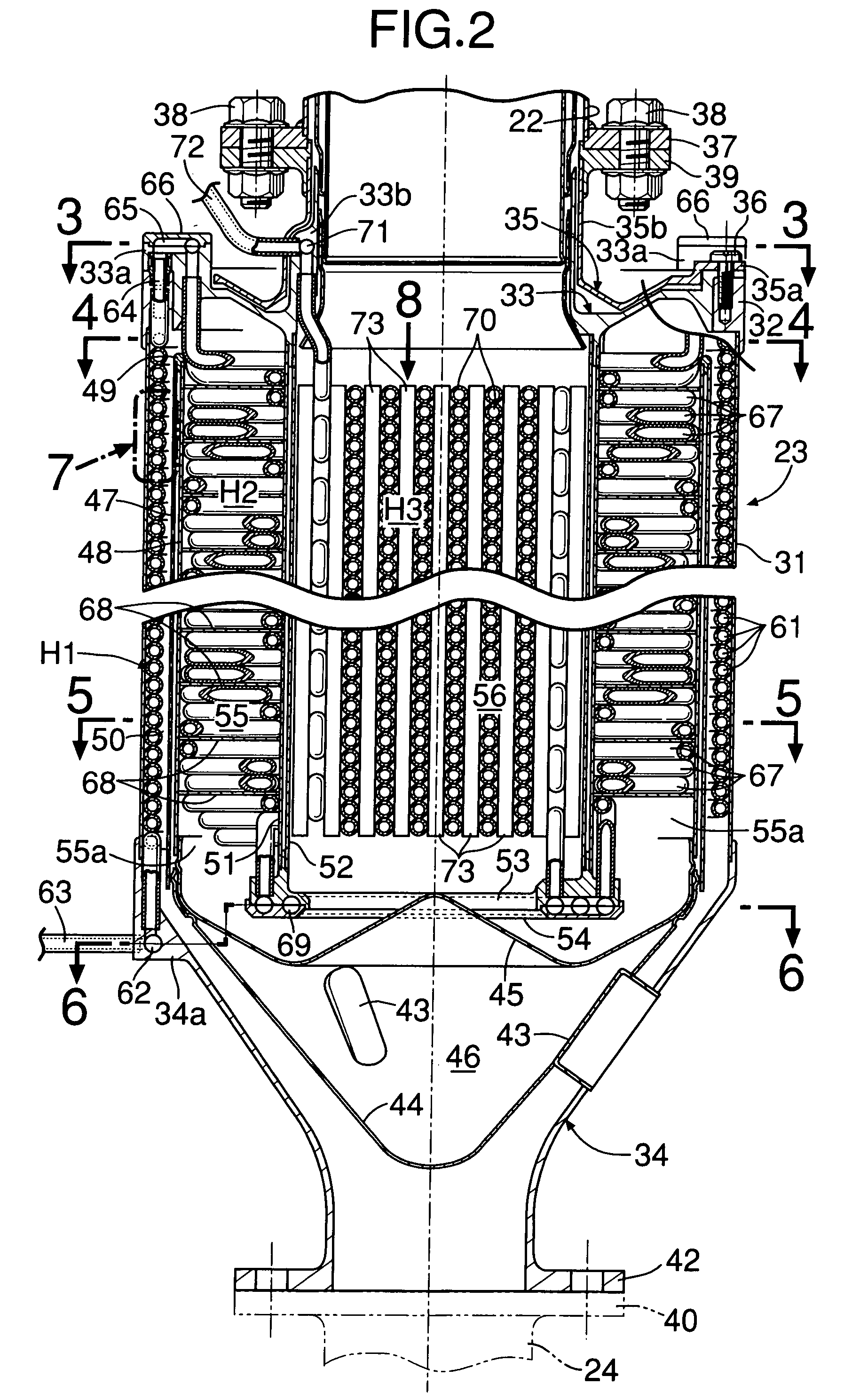
[0047] As shown in FIG. 1, an in-line multicylinder internal combustion engine E includes a cylinder head 12 and a head cover 13 joined to an upper face of a cylinder block 11, and an oil pan 14 joined to a lower face of the cylinder block 11. Pistons 16 slidably fitted in cylinder bores 15 provided in the cylinder block 11 are connected to a crankshaft 18 via connecting rods 17. An intake manifold 21 and an exhaust manifold 22 are respectively connected to intake ports 19 and exhaust ports 20 formed in the cylinder head 12, and an exhaust pipe 24 is connected to the downstream side of the exhaust manifold 22 via an evaporator 23. The evaporator 23 forms a heat exchanger of the present invention, and generates high temperature, high pressure steam by heating water as a heat-absorbing medium with the heat of exhaust gas as a thermal fluid.

[0048] The structure of the evaporator ...


PUM


Abstract

There is provided an evaporator (23) disposed between an exhaust manifold (22) and an exhaust pipe (24), the evaporator (23) including, in sequence from the upstream side toward the downstream side, a first exhaust gas passage (56) having a third stage heat exchanger (H3), a second exhaust gas passage (55) having a second stage heat exchanger (H2), and a third exhaust gas passage (50) having a first stage heat exchanger (H1). Formed in the annular second exhaust gas passage (55) of the second stage heat exchanger (H2) is a spiral passage divided by a spiral heat transfer plate (68), and arranged in a spiral shape so as to follow the heat transfer plate (68) are a plurality of undulating heat transfer tubes (67) that are stacked out of phase. Increasing the exhaust gas passage length by the heat transfer plate (68) and agitating the flow of exhaust gas by the heat transfer tubes (67) enables the opportunity for contact of the exhaust gas with the heat transfer plate (68) and the heat transfer tubes (67) to be increased, thereby enhancing the heat exchange efficiency.

Description

FIELD OF THE INVENTION [0001] The present invention relates to a heat exchanger that has a heat transfer member disposed so as to be in contact with a thermal fluid flowing within a thermal fluid passage while the temperature of the thermal fluid decreases, and that recovers the thermal energy of the thermal fluid with a heat-absorbing medium via the heat transfer member by making the heat-absorbing medium flow within the heat transfer member in a direction opposite to the flow of the thermal fluid. The present invention also relates to a heat exchanger that carries out heat exchange between a thermal fluid flowing through a thermal fluid passage formed in the interior of a casing and a heat-absorbing medium flowing within a heat transfer member disposed in the thermal fluid passage. BACKGROUND ART [0002] Such a heat exchanger is known from Japanese Patent Application Laid open No. 2001-207839 filed by the present applicant. This heat exchanger is an evaporator that generates high t...

Claims


Application Information

Patent Timeline
Patent Type & Authority Applications(United States)
IPC IPC(8): F01N5/02F28D7/00F28D7/02F28D7/08F28D15/02F28F9/22F28F13/12
CPCF01N5/02F01N2240/02F28D7/0075F28D7/022F28D7/024F28D7/08Y02T10/16F28D7/085F28D21/0003F28D2021/0064F28F9/22F28F13/12F28D7/082Y02T10/12
Inventor KOMATSU, HARUHIKOTANAKA, HIROYUKISHINOHARA, MASASHISAITO, BUNICHIIZUMI, HIDEHARU
Owner HONDA MOTOR CO LTD
Why Eureka
Try Eureka