Vacuum switchgear

a switchgear and vacuum technology, applied in the direction of electrical apparatus construction details, conductors, casings/cabinets/drawers, etc., can solve the problem of no longer accelerating charged particles generated by dielectric breakdown, and achieve the effect of preventing damage to devices, and preventing ground faults

Inactive Publication Date: 2005-05-19
HITACHI LTD
View PDF4 Cites 8 Cited by
  • Summary
  • Abstract
  • Description
  • Claims
  • Application Information

AI Technical Summary

Benefits of technology

[0005] An object of this invention is to prevent a dielectric breakdown due to foreign particulates and improve the insulation reliability of devices.
[0007] In this construction, for instance, when particulate foreign matters reach a high electric field area near the conductors, a dielectric breakdown phenomenon occurs only between the conductors and the shield but not between the shield and the vacuum container. Thus, this dielectric breakdown does not result in a ground fault, nor does it lead to a power system failure. More specifically, in the event that a dielectric breakdown phenomenon is caused by particulate foreign matters, the shield and the conductors are instantly brought to the same potential. However, since the shield is insulated from the vacuum container, an electric field between the conductors and the shield disappears, no longer accelerating charged particles generated by the dielectric breakdown. The dielectric breakdown therefore can no longer persist, and the dielectric strength can recover instantly, preventing damages to the devices. This in turn can prevent a ground fault and also prevent the dielectric breakdown phenomenon from providing a cause for a possible power system failure.
[0008] According to the invention it is possible to prevent damages to the devices and a ground fault and to prevent a cause for a possible power system failure.

Problems solved by technology

However, since the shield is insulated from the vacuum container, an electric field between the conductors and the shield disappears, no longer accelerating charged particles generated by the dielectric breakdown.

Method used


Image

  • Vacuum switchgear
  • Vacuum switchgear
  • Vacuum switchgear

Examples


Embodiment Construction

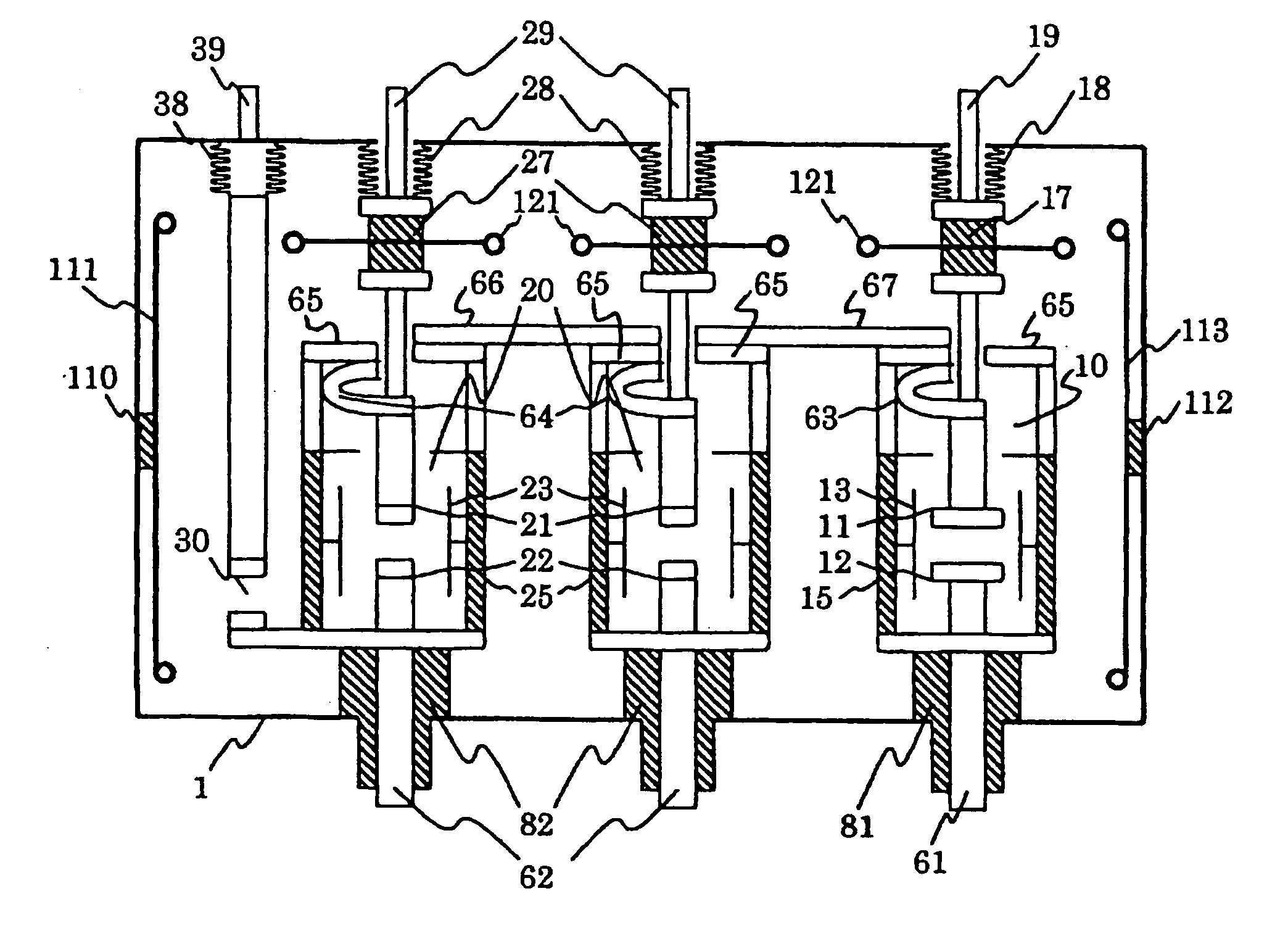
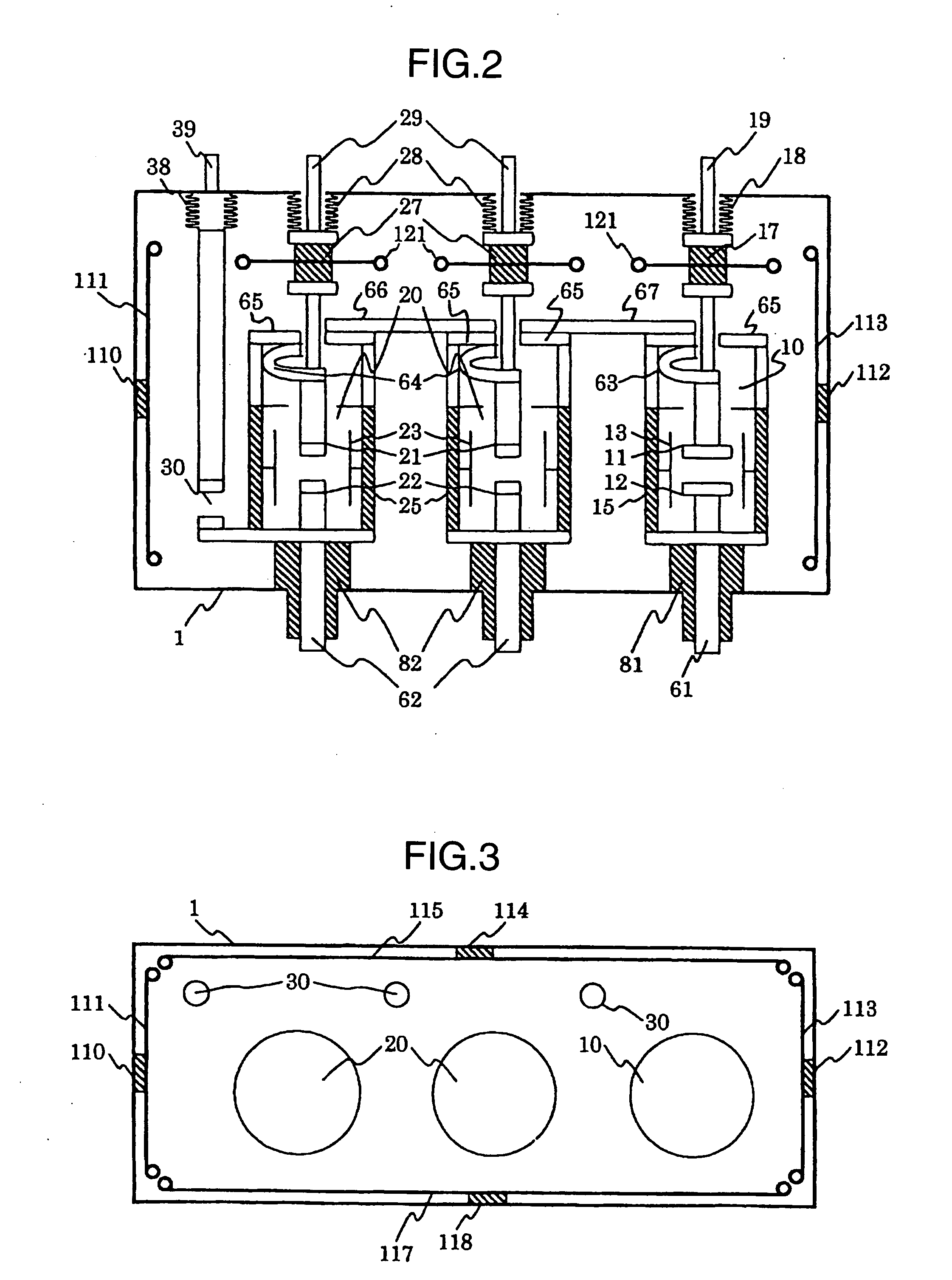
[0013] An embodiment of the invention will be now described with reference to the accompanying drawings. FIG. 1 is a vertical sectional view of a vacuum switchgear showing the embodiment of the invention. In FIG. 1, the vacuum switchgear is represented by one phase of one unit in a power receiving and distribution board comprised of a plurality of units. In this embodiment, a main circuit switching unit 10, an isolator 20, flexible conductors 63, 64, an earthing device 30 and so on are accommodated in vacuum containers 1, 2 that need to be grounded, i.e., in the vacuum containers which are grounded and formed of a metal (stainless steel). A conductor 61 and a main circuit conductor 62 are arranged to extend inside and outside the vacuum containers 1, 2.

[0014] The main circuit switching unit 10 has a movable electrode 11 and a stationary electrode 12 and is installed in the vacuum container 1, separated by a spacer 15 from the isolator 20. An intermediate shield 13 is arranged aroun...


PUM

PropertyMeasurementUnit
resistanceaaaaaaaaaa
vacuumaaaaaaaaaa
voltageaaaaaaaaaa

Abstract

A main circuit switching unit and an isolator are accommodated in a vacuum container. A first conductor and a main circuit conductor are arranged to extend in and out of the vacuum container. A movable electrode of the main circuit switching unit is connected to the first conductor through a first flexible conductor, and a movable electrode of the isolator is connected to the main circuit conductor through a second flexible conductor. A shield is arranged around the first conductor and the main circuit conductor. Another shield is arranged around a connecting portion between the first flexible conductor and the movable electrode of the main circuit switching unit. A still another shield is arranged around the isolator. A further another shield is arranged around the second flexible conductor. These shields are secured to the vacuum container through insulating spacers. This arrangement instantly eliminates a dielectric breakdown phenomenon that occurs at electric field concentrated regions by the shields to prevent a dielectric breakdown caused by particulate foreign matters and thereby improve an insulation reliability of the devices.

Description

BACKGROUND OF THE INVENTION [0001] The present invention relates to a vacuum switchgear and more particularly to a vacuum switchgear, in which a switch having a stationary electrode and a movable electrode is enclosed in a vacuum container that requires grounding. [0002] As a conventional vacuum switchgear, for example, there is a construction, in which a vacuum container accommodates a main circuit switching unit for connecting and disconnecting a main circuit conductor to and from a load side conductor or a bus side conductor and a main circuit / earth selecting unit for connecting the main circuit conductor to and from the bus side conductor or the load side conductor and an earthing conductor and in which the vacuum container is formed of a grounded metal or an insulating material with a grounded layer on its surface. This vacuum container accommodates the main circuit conductor and a part of each of the bus side conductor, the earthing conductor and the load side conductor. Furth...

Claims


Application Information

Patent Timeline
Patent Type & Authority Applications(United States)
IPC IPC(8): H01B1/00H02B13/055H01H1/58H01H31/00H01H33/02H01H33/66H01H33/662H01H33/666H02B13/02H05K5/00H05K9/00
CPCH01H1/5822H01H31/003H01H33/022H01H2033/6668H01H33/6661H01H2033/66284H01H33/66261H01H33/66
Inventor UTSUMI, TOMOAKISATOU, KAZUHIROSHIRONE, TAKASHITSUCHIYA, KENJIKOBAYASHI, MASATO
Owner HITACHI LTD
Why Eureka
Try Eureka