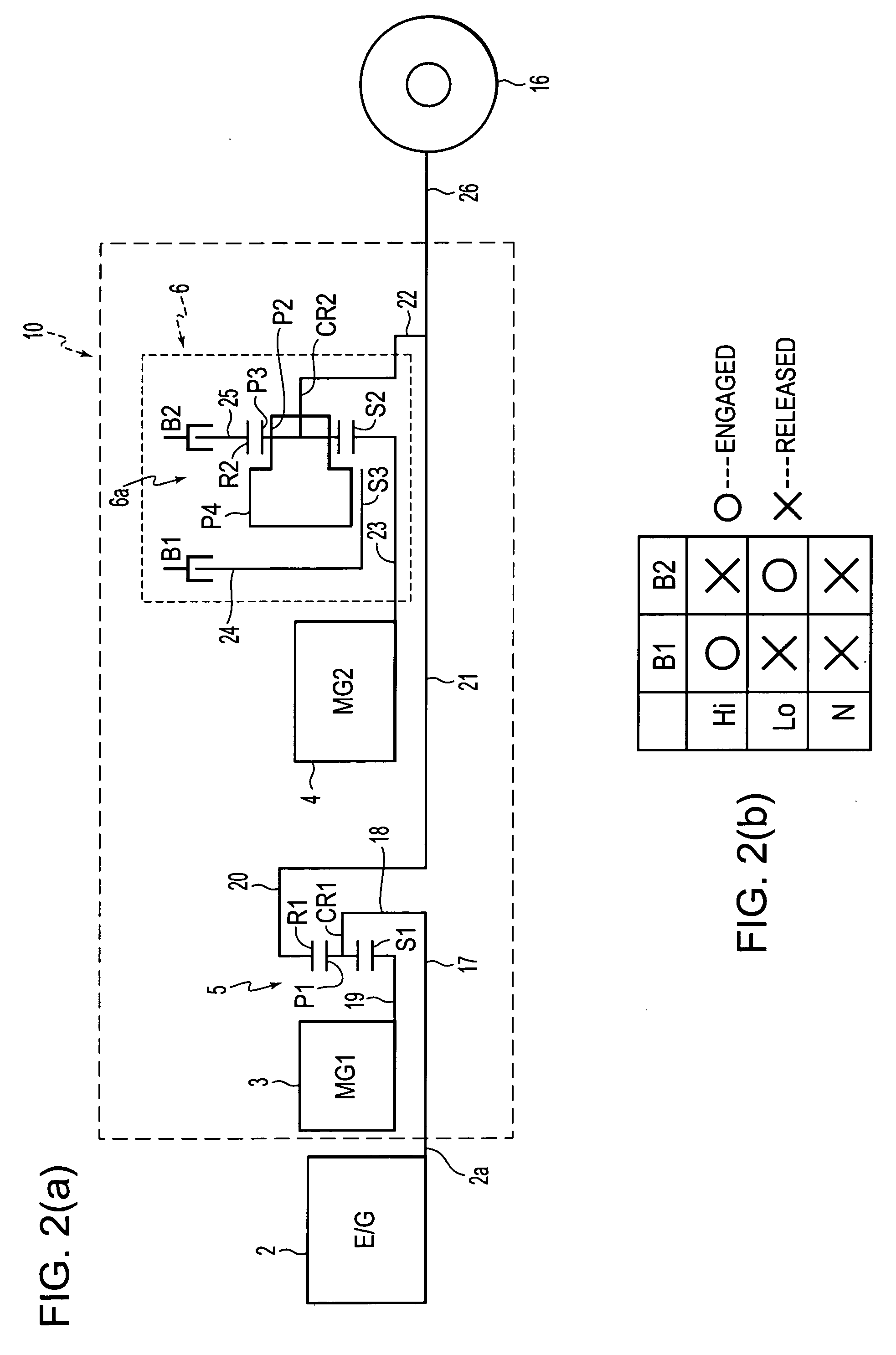
[0008] In order to solve the aforementioned problem, it is conceivable to provide a stepped transmission between the second electric motor and the transfer shaft. For example, if the rotation speed of the second electric motor can be shifted corresponding to a low-to-intermediate vehicle speed region and an intermediate-to-high vehicle speed region, it becomes possible to use the second electric motor at low rotation speeds, so that the second electric motor can be of a compact size and therefore installability of the second electric motor in the vehicle will improve.
[0011] Accordingly, it is an object of the invention to provide a control apparatus of a
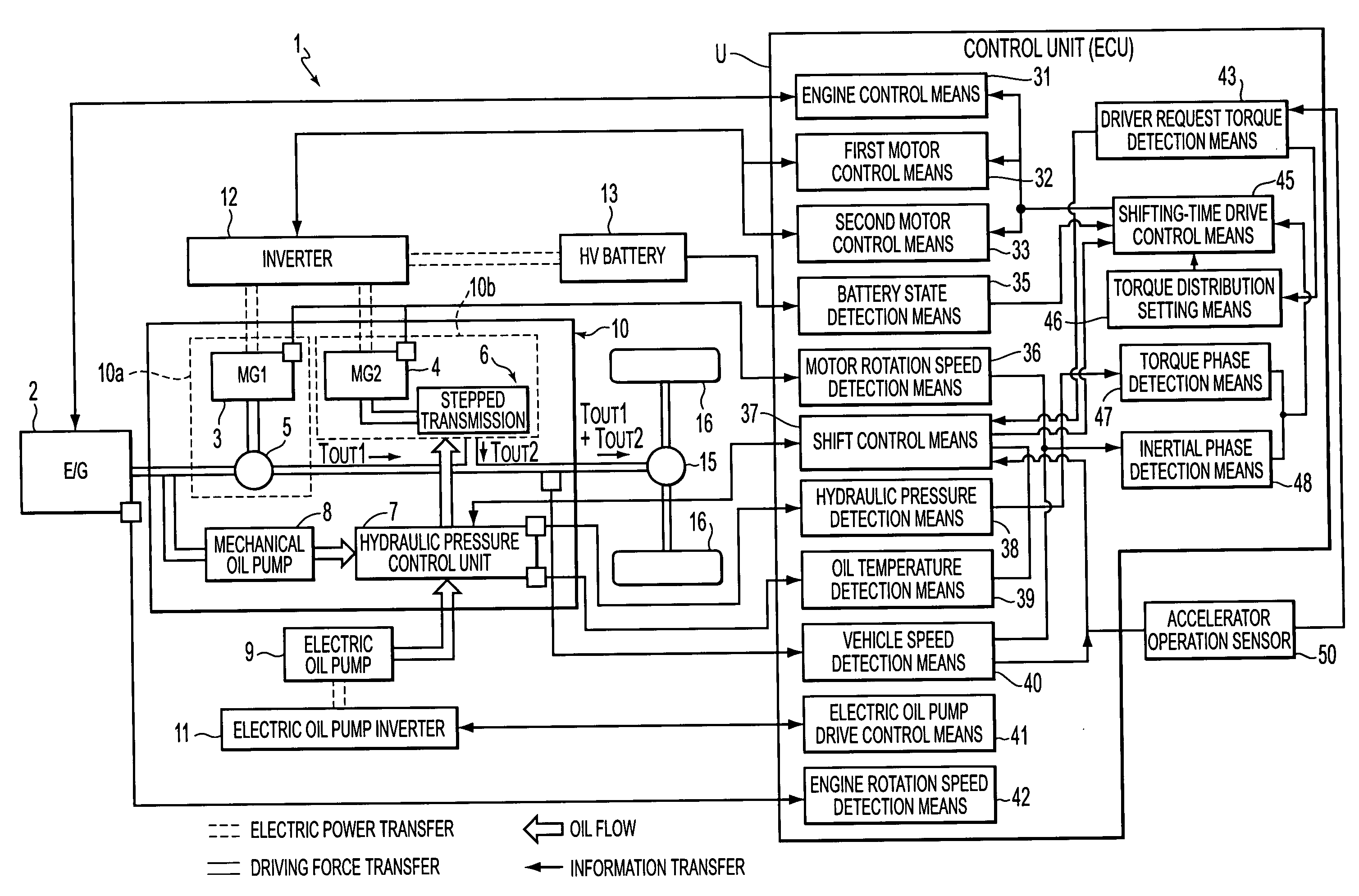
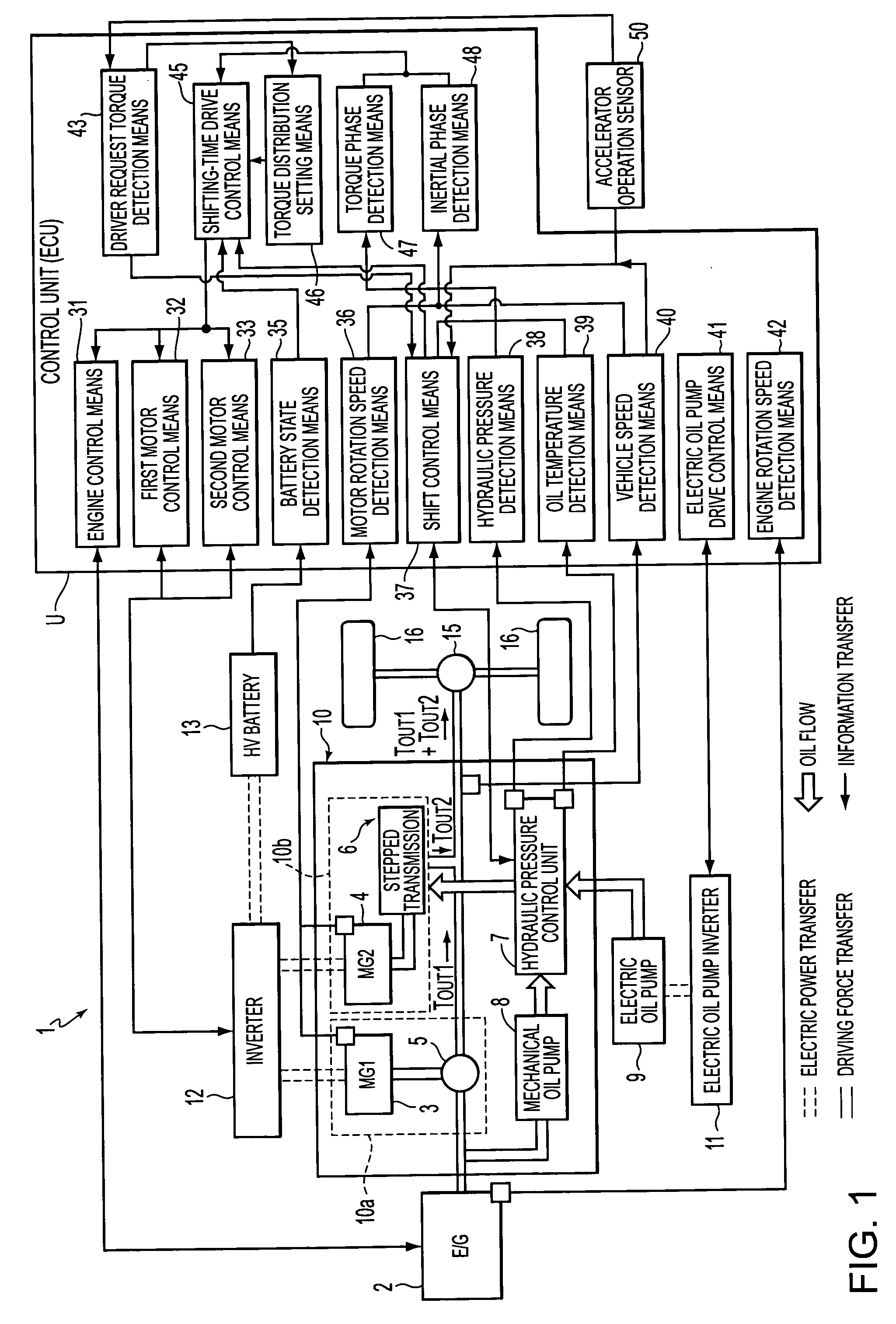
hybrid vehicle which shifts the electric motor output stepwise via a stepped transmission, combines the electric motor output with an engine output, and transfers the combined output to a driving wheel side. The control apparatus is designed to be able to always stably supply an output needed in order to offset torque fluctuations at the time of the shifting of the stepped transmission so as to eliminate or minimize the output fluctuation at the driving wheel side, at the time of the shifting, by relaxing the restrictions on the output increase / decrease amount imposed due to the battery performance and the like, and which thereby solves the aforementioned problems of the related art.
[0012] In a control apparatus of a
hybrid vehicle according to a first exemplary aspect of the invention, if it is determined that there is a need for shifting carried out by a stepped transmission, battery balance control means calculates an amount of increase / decrease in the amount of charge of a battery in accordance with a state of the battery, and changes an
operation point of an engine based on the amount of increase / decrease in the amount of charge, prior to the shifting of the stepped transmission. Therefore, on the side of a second drive unit, the supply of
electric power to a second electric motor is always appropriately performed, regardless of the
state of charge of the battery, so that sufficient amount of driving force of the second electric motor is attained to avoid torque fluctuation at the time of the shifting of the stepped transmission. On the side of a first drive unit, a first electric motor can be appropriately operated within an allowable range of the amount of
battery charge in conjunction with the supplied
electric power or the regenerated electric power, due to the engine driven on the basis of the engine
operation point changed on the basis of the amount of increase / decrease in the
battery charge. Therefore, it becomes possible to minimize the output fluctuations on the driving wheel side at the time of shifting the transmission speed.
[0016] According to a fifth exemplary aspect of the invention, the battery balance control means executes such a returning control so as to resume a torque of the first electric motor and a torque of the engine corresponding to the operation point of the engine set prior to the shifting based on the state of the battery after the shifting of the stepped transmission has ended. Therefore, the engine torque and the first
motor torque, whose balance has changed during the shifting, are quickly returned to the values occurring prior to the shifting. For example, the engine torque increased during the shifting is promptly reduced to curb fuel consumption, so that the fuel economy will improve.
[0017] According to a sixth exemplary aspect of the invention, the battery balance control means calculates an electric
power consumption that is needed for the shifting to be performed, and determines whether it is possible to output the electric
power consumption from the battery. If it is determined that it is possible to output the amount of electric power from the battery, the battery balance control means avoids a change of the operation point of the engine. If it is determined that that it is impossible to output the amount of electric power from the battery, the battery balance control means executes such a control as to change the operation point of the engine. Therefore, the control apparatus is able to execute an always appropriate control in accordance with the state of the battery.

