Plasma source with segmented magnetron cathode

a technology of magnetron cathode and plasma source, which is applied in the direction of electrolysis components, vacuum evaporation coatings, coatings, etc., can solve the problems of poor target utilization, inability to control and difficulty in controlling the uniformity of sputtered film and the density of plasma generated during pvd

Inactive Publication Date: 2005-05-19
ZOND
View PDF27 Cites 145 Cited by
  • Summary
  • Abstract
  • Description
  • Claims
  • Application Information

AI Technical Summary

Problems solved by technology

Independently controlling the uniformity of the sputtered film and the density of the plasma generated during PVD becomes more difficult as the size of the workpiece increases.
However, processing large workpieces can result in problems, such as poor target utilization, target cooling problems, and non-uniform coating of the workpieces.
However, moving the m...

Method used


Image

  • Plasma source with segmented magnetron cathode
  • Plasma source with segmented magnetron cathode
  • Plasma source with segmented magnetron cathode

Examples


Embodiment Construction

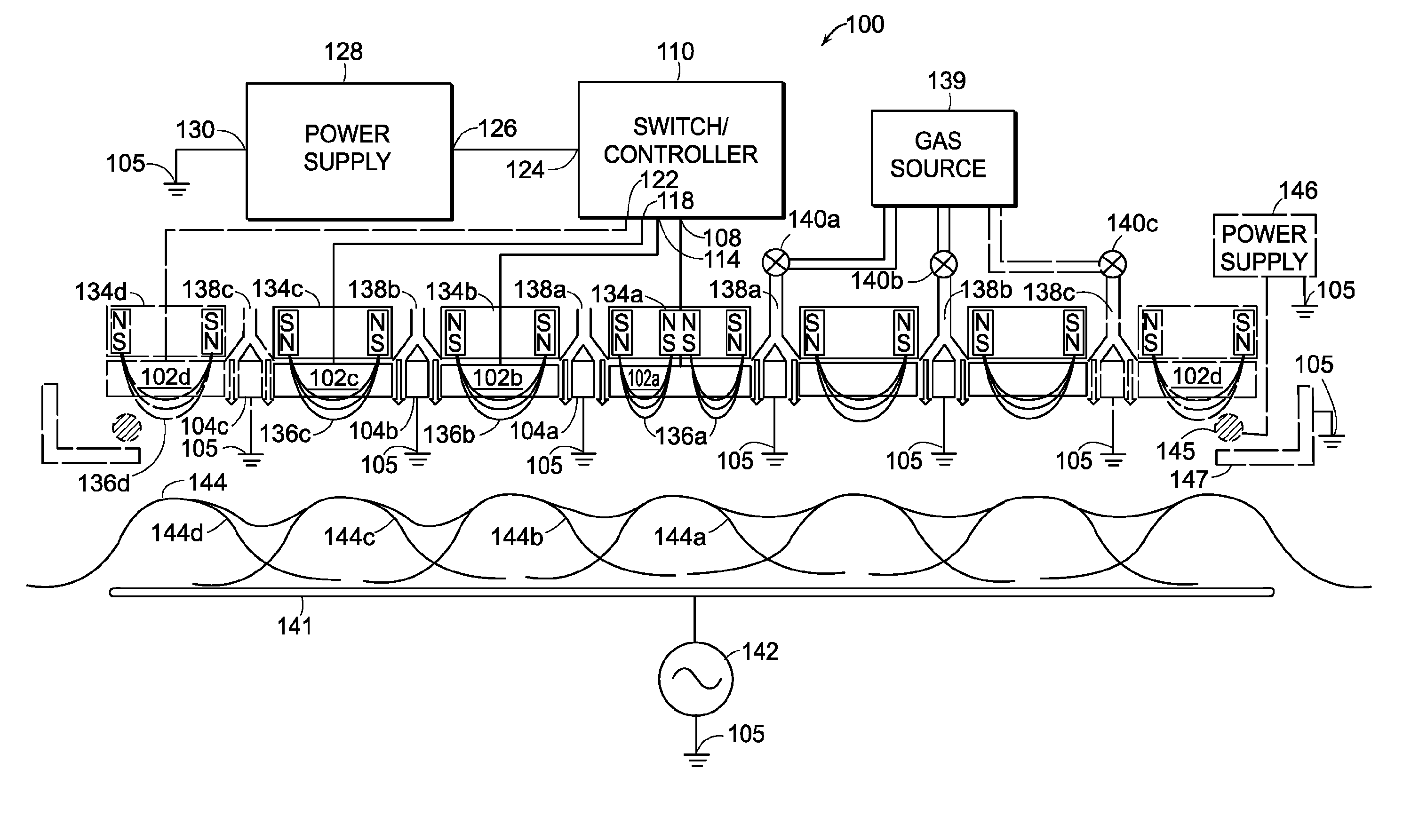
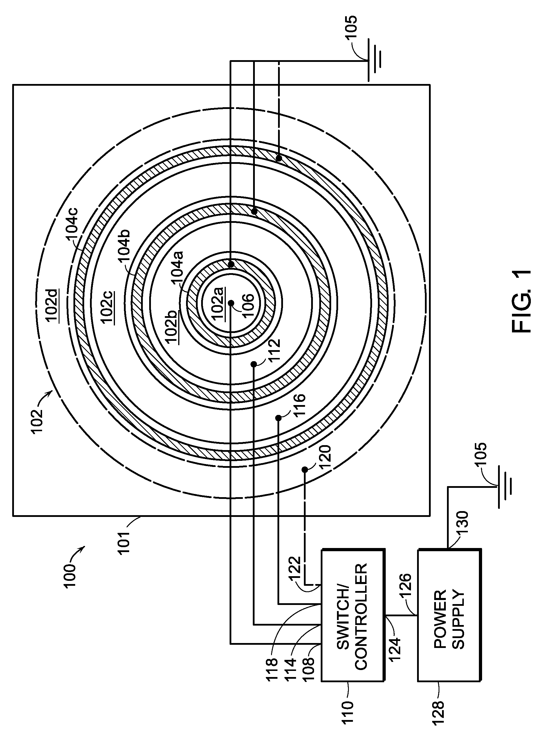
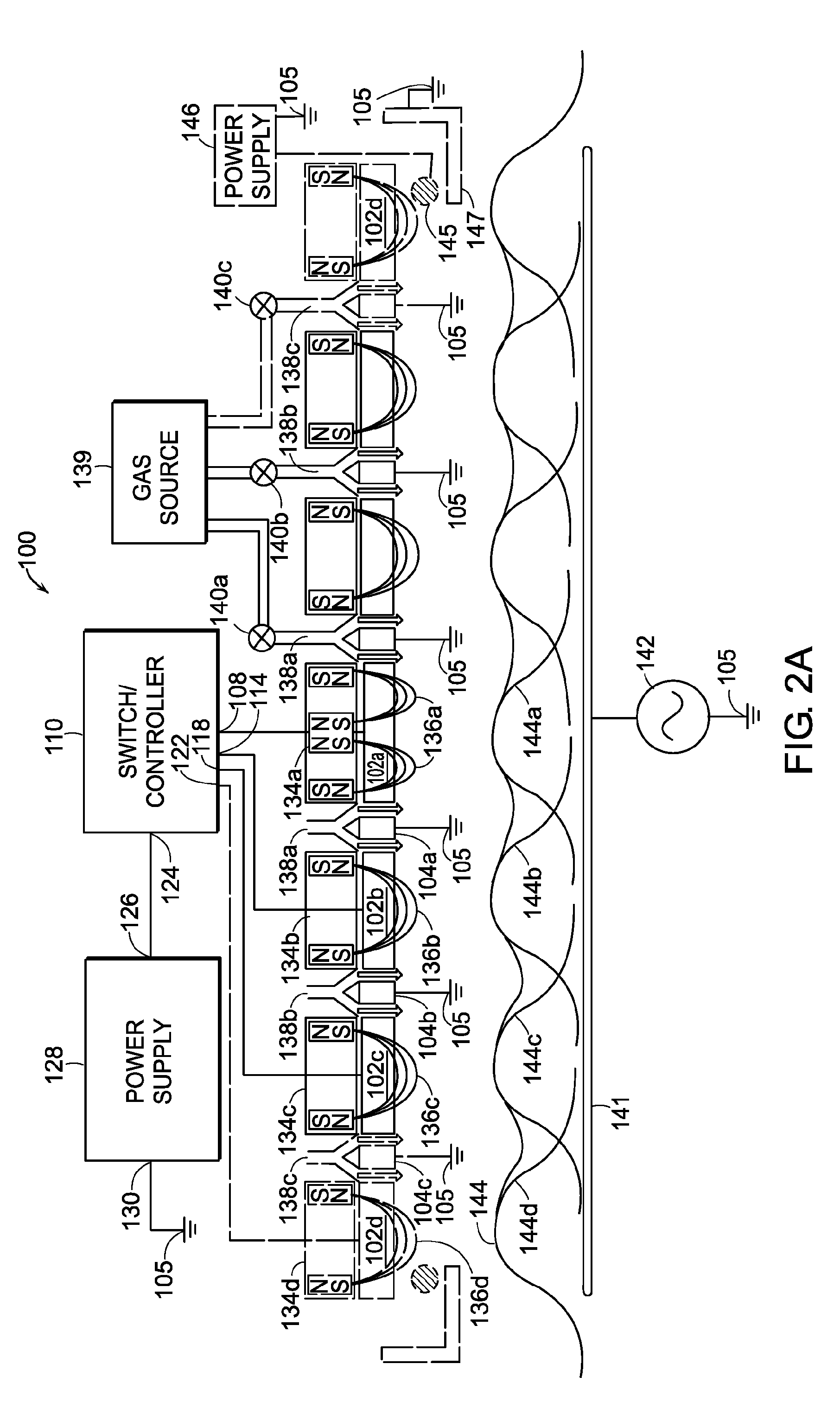
[0021] The present invention relates to plasma systems having multiple or segmented magnetron cathodes instead of one single magnetron cathode. A plasma generated by a plasma system having a segmented magnetron cathode design according to the present invention creates a more uniform coating on a substrate at given level of plasma density than a plasma that is generated by a known plasma system having a single magnetron cathode geometry. The uniformity of a thin film generated with a plasma system having multiple magnetron cathode segments is relatively high because each of the multiple magnetron cathode segments can independently control a film thickness in a small localized area of the workpiece in order to generate a more uniform coating on the entire workpiece.

[0022] Increasing the number of magnetron cathode segments increases the control over the coating thickness. The sputtered material generated by the segmented magnetron cathode can also be directed to different locations i...


PUM

PropertyMeasurementUnit
Carrier concentrationaaaaaaaaaa
Timeaaaaaaaaaa
Poweraaaaaaaaaa

Abstract

A plasma source includes a chamber for containing a feed gas. An anode is positioned in the chamber. A segmented magnetron cathode comprising a plurality of electrically isolated magnetron cathode segments is positioned in the chamber proximate to the anode. A power supply is electrically connected to an electrical in-put of a switch. A respective one of the plurality of electrical out-puts of the switch is electrically connected to a respective one of the plurality of magnetron cathode segments. The power supply generates a train of voltage pulses that ignites a plasma from the feed gas. Individual voltage pulses in the train of voltage pulses are routed by the switch in a predetermined sequence to at least two of the plurality of magnetron cathode segments.

Description

CROSS REFERENCE TO RELATED APPLICATIONS [0001] This patent application claims priority to U.S. Provisional Patent Application Ser. No. 60 / 481,671, filed on Nov. 19, 2003, the entire disclosure of which is incorporated herein by reference.BACKGROUND OF INVENTION [0002] Physical Vapor Deposition (PVD) is a plasma process that is commonly used in the manufacturing of many products, such as semiconductors, flat panel displays, and optical devices. Physical vapor deposition causes ions in a plasma to dislodge or sputter material from a target. The dislodged or sputtered target material is then deposited on a surface of a workpiece to form a thin film. [0003] Independently controlling the uniformity of the sputtered film and the density of the plasma generated during PVD becomes more difficult as the size of the workpiece increases. In magnetron sputtering, large targets are typically required to sputter coat large workpieces. However, processing large workpieces can result in problems, s...

Claims


Application Information

Patent Timeline
IPC IPC(8): C23C14/00C23C14/34C23C14/35C23C14/54H01J37/34
CPCC23C14/0063C23C14/345C23C14/352C23C14/542H01J37/3405H01J37/3408H01J37/347H01J37/342H01J37/3429H01J37/3438H01J37/3444H01J37/3455H01J37/3458H01J37/3411
Inventor CHISTYAKOV, ROMAN
Owner ZOND
Why Eureka
Try Eureka