High print quality inkjet printhead

a high-quality, inkjet printing technology, applied in printing, other printing apparatus, etc., can solve the problems of vapor bubble collapse in the firing chamber in a small but violent way, heater resistors are particularly susceptible to damage, degradation and failure of heater resistors and electrical conductors,

Inactive Publication Date: 2005-05-19
HEWLETT PACKARD DEV CO LP
View PDF38 Cites 12 Cited by
  • Summary
  • Abstract
  • Description
  • Claims
  • Application Information

AI Technical Summary

Problems solved by technology

Following removal of electrical power from the heater resistor, the vapor bubble collapses in the firing chamber in a small but violent way.
Components within the printhead in the vicinity of the vapor bubble collapse are susceptible to fluid mechanical stresses (cavitation) as the vapor bubble collapses, thereby allowing ink to crash into the ink firing chamber components.
The heater resistor is particularly susceptible to damage from cavitation.
Thermal inkjet ink is chemically reactive, and prolonged exposure of the heater resistor and its electrical interconnections to the ink will result in a degradation and failure of the heater resistor and electrical conductors.
The foregoing protection layers, however, tend to increase the inherent turn-on energy of the heater resistor required for ejecting ink drops due to the insulating properties of the layers.
Each electrical conductor, despite its good conductivity, imparts an undesirable amount of resistance in the path of the heater resistor.
This undesirable parasitic resistance uselessly dissipates a portion of the electrical energy which otherwise would be available to the heater resistor thereby contributing to the heat gain of the printhead.
If the heater resistance is low, the magnitude of the current drawn to nucleate the ink vapor bubble will be relatively large resulting in the amount of energy wasted in the parasitic resistance of the electrical conductors being significant relative to that provided to the heater resistor.
That is, if the ratio of resistances between that of the heater resistor and the parasitic resistance of the electrical conductors (and other components) is too small, the efficiency (and the temperature) of the printhead suffers with the wasted energy.
So, designers of ink-jet printheads are faced with the problem of more drop generators (with their associated heater resistors) disposed over a smaller area of printhead being operated at an increased frequency.
This approach, however, leads to an unacceptably higher cost, since processed semiconductor material costs rise exponentially with increased area.
It is possible to control printhead temperature by slowing the rate of heater resistor activation n the duty cycle of the heating pulses can be lower fi but this leads to a lower page per minute printing delivery and is unacceptable to the user of the printing device.

Method used


Image

  • High print quality inkjet printhead
  • High print quality inkjet printhead
  • High print quality inkjet printhead

Examples


Embodiment Construction

[0031] In order to realize a high quality print output, high drop generator density, and high throughput without high printhead temperatures, control and reduction of energy input for small closely packed drop generators must be undertaken. To this end several unique improvements have been made and in some instances, combined, to yield improved print quality.

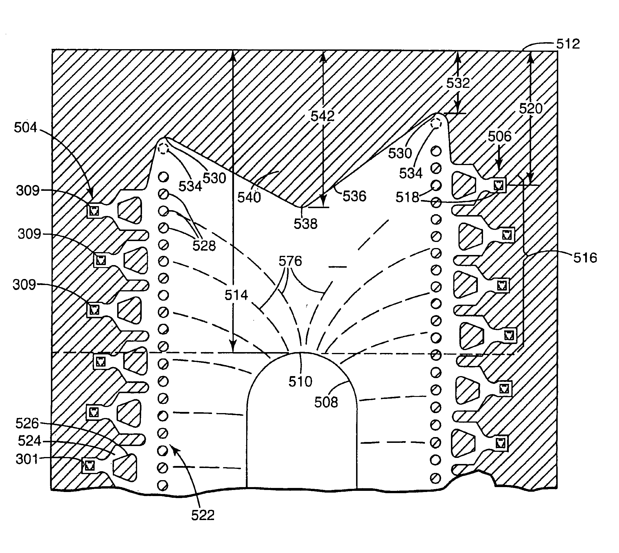
[0032] There are two major sources of heat generation h the heater resistor itself and the combined resistance of the energizing power thin film conductors and the thin film ground return conductors disposed on the semiconductor substrate. Each conventional heater resistor has a resistance of approximately 40Ω including the parasitic resistance of the thin film conductors on the substrate. With a high density of heater resistors for the drop generators, there exists a high density of thin film conductors with attendant parasitic resistance. In a conventional implementation, the parasitic resistance associated with each heater r...


PUM


Abstract

Several improvements have been made in inkjet print cartridges to realize 5 ng drop weights at ejection frequencies of 18 KHz. These improvements include small nozzle openings, improved heater resistor efficiency, and better ink supply reliability.

Description

BACKGROUND OF THE INVENTION [0001] The present invention relates generally to inkjet printing devices, and more particularly to a print cartridge providing high quality print output and adapted for use in inkjet printing devices. The present disclosure may contain material related to the inventions disclosed in U.S. patent application Ser. Nos. {attorney docket no. 10981497} “Segmented Resistor Drop Generator For InkJet Printing”, {attorney docket no. 10991830} “Redundant Input Signal Paths For An InkJet Print Head”, {attorney docket no. 10991241} “InkJet Printhead With Flow Control Manifold And Columnar Structures”, {attorney docket no. 10982182} “Asymmetric Ink Emitting Orifices For Improved Inkjet Drop Formation”, {attorney docket no. 10990590} “High Drop Generator Density PrintHead”, {attorney docket no. 10990591} “Shared Multiple Terminal Ground Returns For An Inkjet Printhead”, {attorney docket no. 10990593} “High Thermal Efficiency InkJet Printhead”, and {attorney docket no. ...

Claims


Application Information

Patent Timeline
Patent Type & Authority Applications(United States)
IPC IPC(8): B41J2/05B41J2/14
CPCB41J2/04541B41J2/04543B41J2/0458B41J2/1404B41J2/14072B41J2002/14475B41J2/14129B41J2002/14177B41J2002/14387B41J2002/14403B41J2002/14467B41J2/1412
Inventor CLELAND, TODD S.MAZE, ROBERT C.MILLER, MICHAEL D.PRASAD, RAMABROWNING, ROBERT N.K.OUGHTON, DALE R.TORGERSON, JOSEPH M.SAUL, KENNETH D.HAGER, MICHAEL B.COLLINS, DOUGLAS M.FIELD, LESLIE A.HOEN, STORRS T.BARTH, PHILLIP W.
Owner HEWLETT PACKARD DEV CO LP
Why Eureka
Try Eureka