Liquid crystal display modul
- Summary
- Abstract
- Description
- Claims
- Application Information
AI Technical Summary
Benefits of technology
Problems solved by technology
Method used
Image

Examples
first embodiment
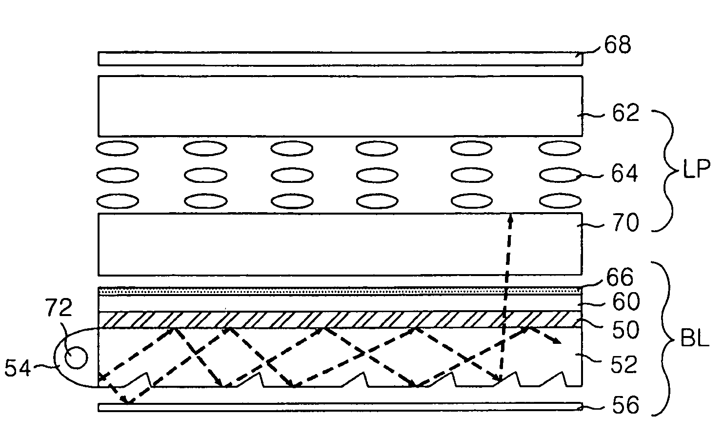
[0049]FIG. 4 is a sectional view representing a liquid crystal display module according to the present invention.
[0050] Referring to FIG. 4, a liquid crystal display module according to a first embodiment of the present invention includes a backlight unit BL and a liquid crystal display panel LP located on the backlight unit BL.
[0051] The backlight unit BL includes a lamp 72 generating light, a lamp housing 54 equipped with the lamp 72, a light guide panel 52 to convert the light being incident from the lamp 72 into a surface light, a low refractive index layer 50 disposed on an upper surface of the light guide panel 52, optical sheets 60 disposed on the low refractive index layer 50 in order to increase the efficiency of the light incident on the liquid crystal display panel LP, and a reflective plate 56 disposed on a lower surface of the light guide panel 52 to reflect the light emitted to the lower surface of the light guide panel 2 to a display panel.
[0052] The low refractive ...
second embodiment
[0066]FIG. 5 is a sectional view representing a liquid crystal display module according to the present invention.
[0067] Referring to FIG. 5, the liquid crystal display module according to the second embodiment of the present invention, when compared with the liquid crystal display module shown in FIG. 4, has the lower substrate of the liquid crystal removed and has the same components except that a plurality of optical sheets, a polarizer and a plurality of electrodes are formed on the light guide panel.
[0068] The light guide panel 52 is made of a material which has a relatively high refractive index, i.e. the first refractive index n1. The low refractive index layer 50 is made of a material which has a lower refractive index (n2) than the light guide panel 52. The low refractive index layer 50 is disposed on the light guide panel 52. This low refractive index layer 50 causes the light to be totally reflected on the border area between the light guide panel 52 and the low refractiv...
third embodiment
[0073]FIG. 6 is a sectional view representing a liquid crystal display module according to the present invention.
[0074] Referring to FIG. 6, the liquid crystal display module according to the third embodiment of the present invention, when compared with the liquid crystal display module shown in FIG. 4, has the same components except that a condensing device (condenser) is included in the incidence part of the light guide panel.
[0075] The condensing device 80 is formed of a plurality of prism patterns between the lamp 72 and the light guide panel 52 so as to reduce the light loss generated through an opening between the lamp 72 and the light guide panel 52. That is, the condensing device 80 condenses the light generated from the lamp 72 and the light reflected by the lamp housing 54. The condensed light is incident to the light guide panel 52 to be able to reduce the gap between the first refractive index (n1) of the light guide panel 52 and the second refractive index (n2) of the ...
PUM
 Abstract
Description
Claims
Application Information
 - R&D
- Intellectual Property
- Life Sciences
- Materials
- Tech Scout
- Unparalleled Data Quality
- Higher Quality Content
- 60% Fewer Hallucinations
Browse by: Latest US Patents, China's latest patents, Technical Efficacy Thesaurus, Application Domain, Technology Topic, Popular Technical Reports.
© 2025 PatSnap. All rights reserved.Legal|Privacy policy|Modern Slavery Act Transparency Statement|Sitemap|About US| Contact US: help@patsnap.com