Equaliser, or phase plug, for electro-acoustic transducers
a technology of electro-acoustic transducers and equalisers, which is applied in the direction of electrical transducers, frequency/directions obtaining arrangements, and transducer casings/cabinets/supports, etc. it can solve the problems of difficult elimination of resonance phenomena, disadvantageous loss of efficiency, and high cost of said pps , to prevent possible phase cancellation
Inactive Publication Date: 2005-05-19
BRAZILIAN SPACE AGENCY
View PDF14 Cites 20 Cited by
- Summary
- Abstract
- Description
- Claims
- Application Information
AI Technical Summary
Benefits of technology
[0024] An aim of the present invention is to eliminate the aforesaid drawbacks making available an equaliser, or phase plug, for electro-acoustic transducers that is able to move beyond the audible band any resonance generated by the slots.
[0026] A further aim of the present invention is to make available a phase plug that eliminates high frequency resonance and simultaneously prevents the generation of stationary waves between PP and membrane.
Problems solved by technology
First of all, said PPs are extremely costly and complicated to assemble, since they must be constructed of multiple pieces (generally, “n” if “n” is the number of slots).
Secondly, such an arrangement of the slots generates resonance phenomena which are difficult to eliminate, especially at high frequencies (over 10 kHz).
Therefore, although a PP with radial symmetry has an undoubted advantage in terms of construction simplicity, it has a disadvantageous loss of efficiency, especially at high frequencies.
Method used
View moreImage
Smart ImageViewing Examples
Examples
first embodiment
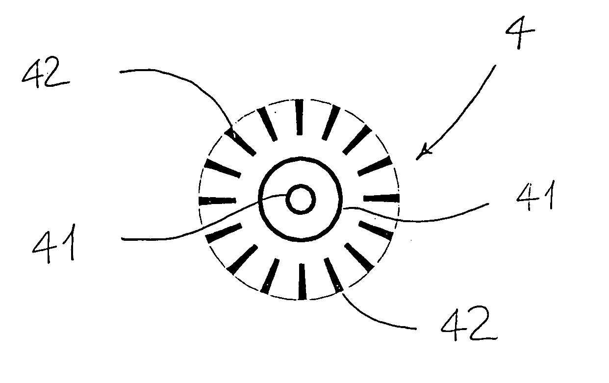
[0030]FIG. 1 shows a top view of a phase plug according to the invention
second embodiment
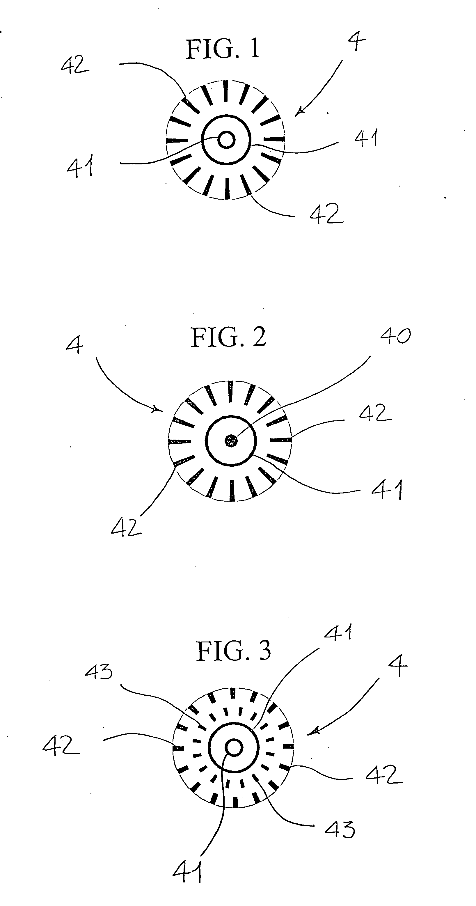
[0031]FIG. 2 shows a top view of a phase plug according to the invention;
third embodiment
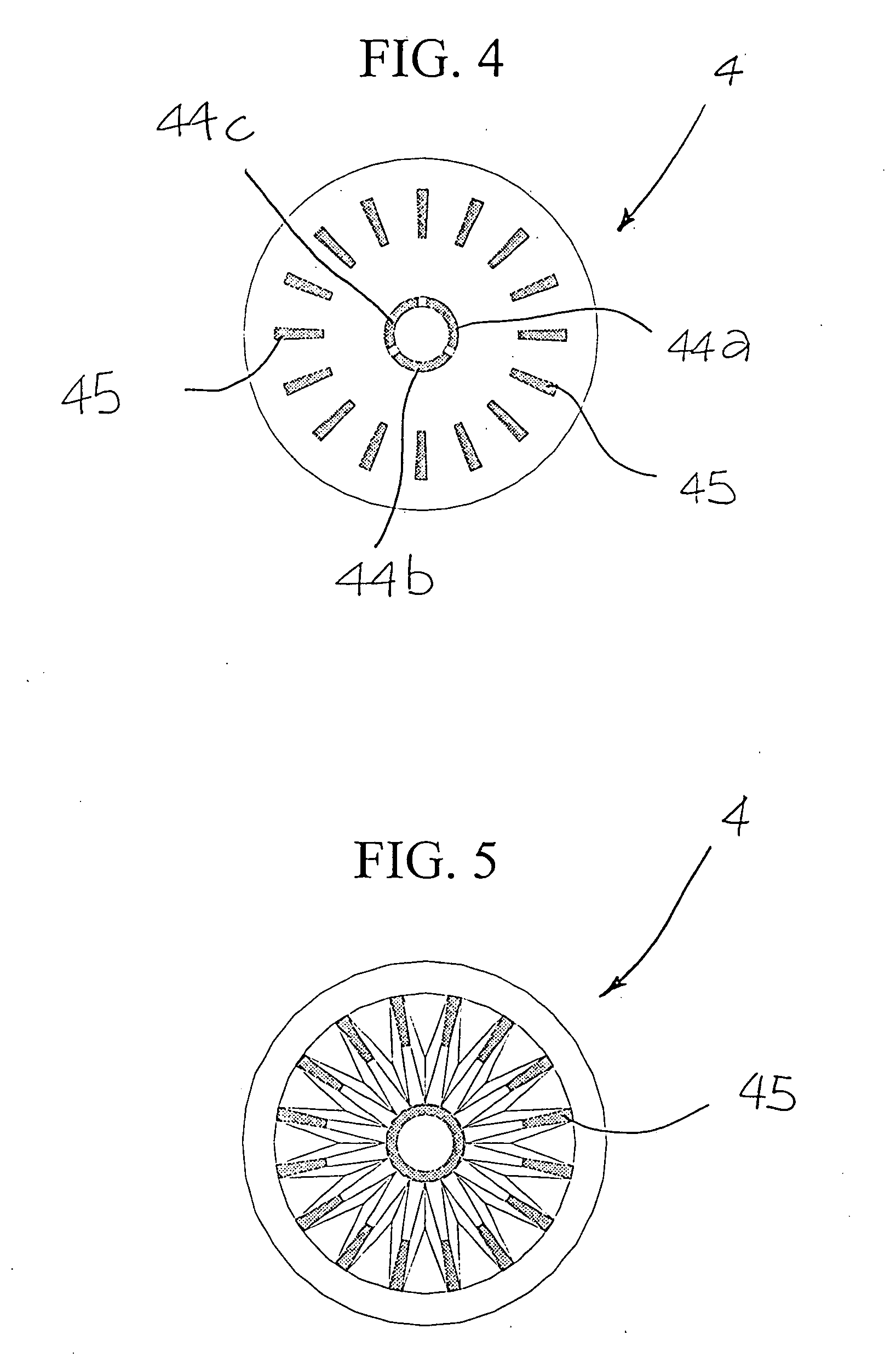
[0032]FIG. 3 shows a top view of a phase plug according to the invention.
Login to View More PUM
 Abstract
Equaliser (4) or phase plug, for electro-acoustic transducers (1), having at least a central hole (40), and or a first series of openings (41), or slots, in the from of concentric rings, coaxial to an axis (4a) of symmetry of the phase plug (4). Said phase plug is characterised in that it has at least a second series of radial slots (42) positioned externally to said hole (40) or to said first series of slots (41). In the phase plug (4) has a third series of radial slots (43) interposed between said first and second series (41;42).
Description
TECHNICAL FIELD AND BACKGROUND ART [0001] The present invention relates to an equaliser, or phase plug, for electro-acoustic transducers, having at least a central hole and / or a first series of openings, or slots, in the form of concentric rings, coaxial to an axis of symmetry of the equaliser. [0002] As is well known, equalisers, better known as “Phase Plug” (PP), are inserted within electro-acoustic transducers designed for sound reproduction, commonly known by the term “Compression Drivers” (CD). [0003] A CD comprises a static magnetic circuit with axial symmetry, obtained using a permanent magnet, for instance with annular shape, interposed between two plates made of ferromagnetic material, one of which, called central pole, has a holed expansion which is inserted in through cavities of the magnet and of the other plate, which is thus annularly positioned relative to said expansion. [0004] Between the expansion of the central pole and the annular plate is obtained an annular air...
Claims
Login to View More Application Information
Patent Timeline
 IPC IPC(8): H04R1/30H04R1/34
CPCH04R1/345H04R1/30
Inventor MANZINI, ANDREAPRATI, STEFANOSTORCHI, UMBERTO
Owner BRAZILIAN SPACE AGENCY
Features
- R&D
- Intellectual Property
- Life Sciences
- Materials
- Tech Scout
- Unparalleled Data Quality
- Higher Quality Content
- 60% Fewer Hallucinations
Learn More Browse by: Latest US Patents, China's latest patents, Technical Efficacy Thesaurus, Application Domain, Technology Topic, Popular Technical Reports.
© 2025 PatSnap. All rights reserved.Legal|Privacy policy|Modern Slavery Act Transparency Statement|Sitemap|About US| Contact US: help@patsnap.com


