Fluid system coupler

a technology of fluid system and coupler, which is applied in the field of coupler, can solve the problems of requiring spill cleanup, affecting the overall efficiency of tissue processing system, and consequential instrument down time,

Active Publication Date: 2005-05-19
SAKURA FINETEK U S A
View PDF5 Cites 15 Cited by
  • Summary
  • Abstract
  • Description
  • Claims
  • Application Information

AI Technical Summary

Benefits of technology

[0007] The present invention alleviates to a great extent the disadvantages of the known devices for providing fluids such as reagents to processing systems requiring the fluids. The preferred example provided is of couplers providing a fluid connection between a fluid container and a tissue processing system, such as may be used in pathology or histolo...

Problems solved by technology

There are various disadvantages of these prior systems.
For example, manually pouring into (or draining) reagent vats suffers a disadvantage being time consuming and requiring pouring accuracy, decreasing the overall efficiency of the tissue processing system.
Another disadvantage is that manual operations can be sloppy, requiring clean up of spills and consequential instrument down time.
A further disadvantage is that care is required in selecting the correct reagent, increasing the possibility that reagents may be po...

Method used


Image

  • Fluid system coupler
  • Fluid system coupler
  • Fluid system coupler

Examples


Embodiment Construction

[0023] In the following paragraphs, the present invention will be described in detail by way of example with reference to the figures. Throughout this description, the preferred embodiment and examples shown should be considered as exemplars, rather than as limitations on the present invention. As used herein, the “present invention” refers to any one of the embodiments of the invention described herein, and any equivalents. Furthermore, reference to various feature(s) of the “present invention” throughout this document does not mean that all claimed embodiments or methods must include the referenced feature(s).

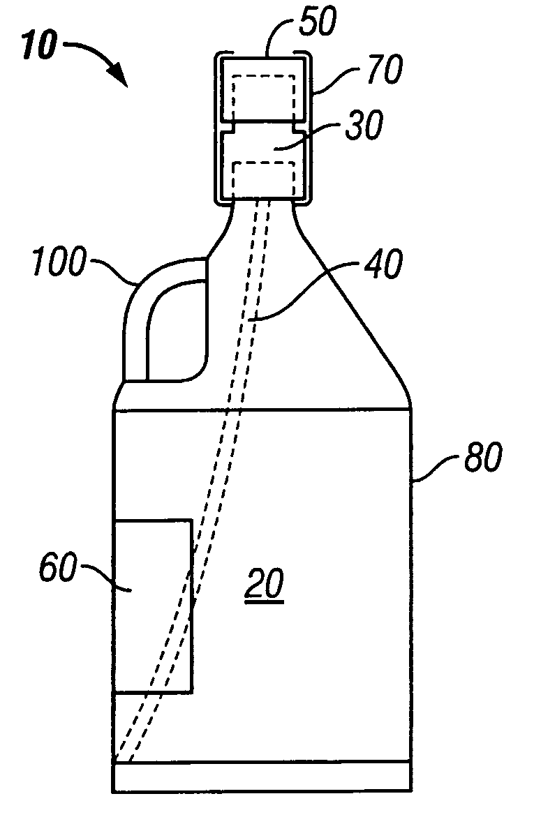
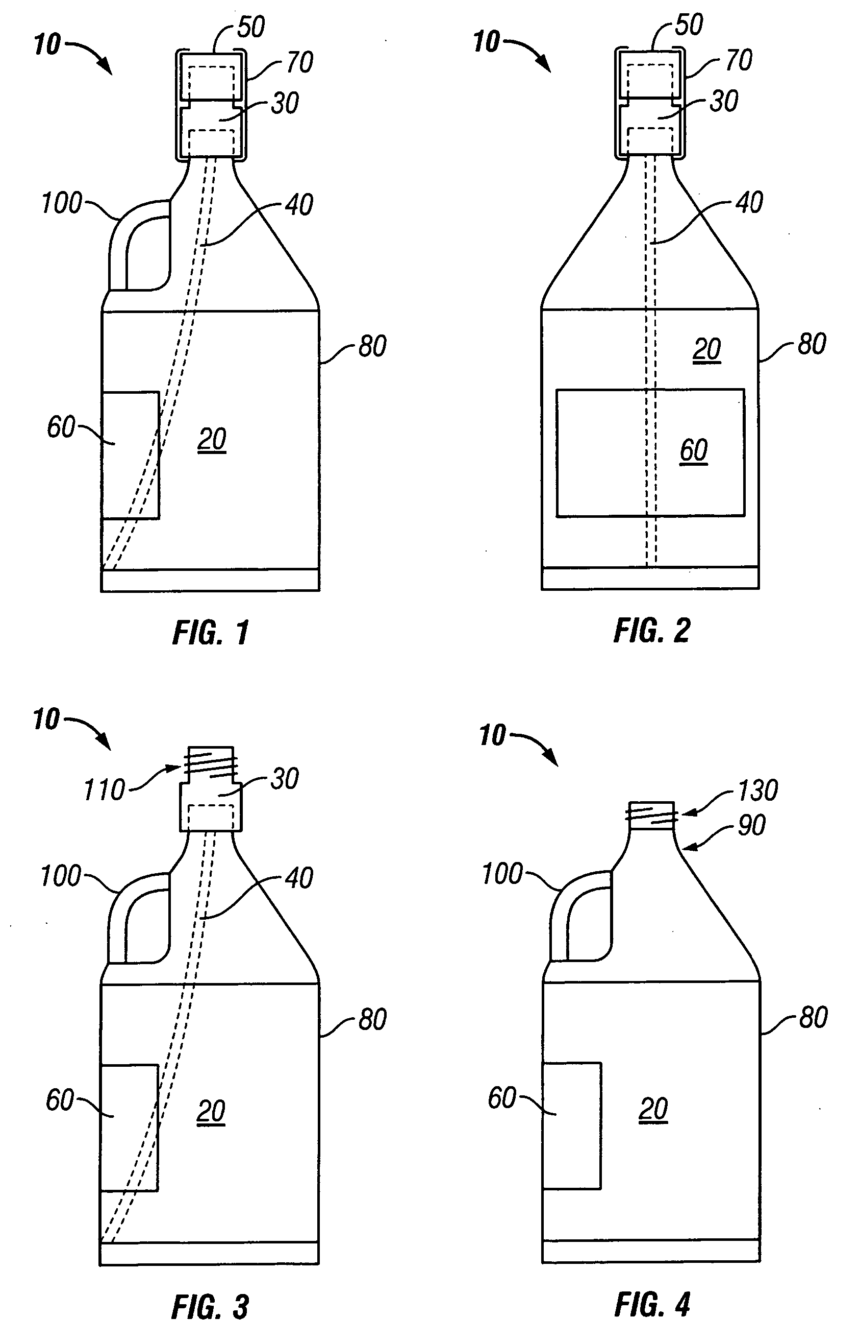
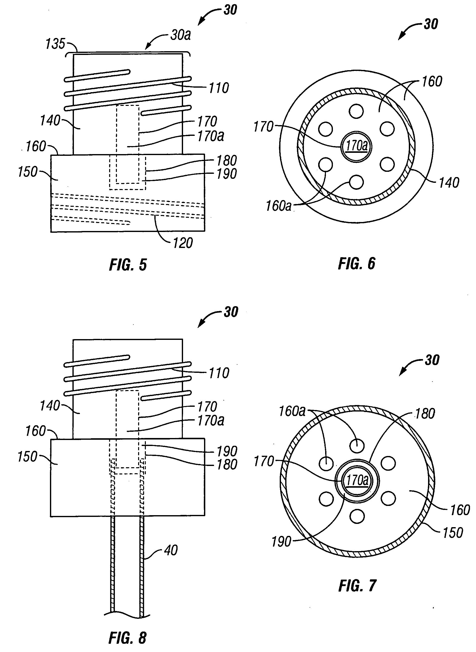
[0024] Referring to FIGS. 1 and 2, an embodiment of a fluid container assembly 10 according to present invention will be described. Generally speaking, the fluid container assembly 10 comprises fluid container 20, coupler 30, tube 40 and cap 50. Coupler 30 illustrates an example of a coupler in accordance with the present invention that provides fluid communication between t...


PUM


Abstract

A tissue processing system includes a tissue processor for processing tissue using reagent fluids, a fluid container and a coupler providing bi-direction fluid communication between the tissue processor and the fluid container. The coupler includes first and second cylindrical rings separated by a wall and a fluid conduit disposed within the first and second cylindrical rings that pass through the wall, thereby providing fluid communication from the fluid container to the tissue processor. Fluid is returned from the tissue processor to the fluid container via at least one fluid return aperture in the wall that separates the first and second cylindrical rings.

Description

FIELD OF THE INVENTION [0001] The present invention is directed to a coupler providing fluid communication between a container and a tubing system, as may be used in instruments requiring reagent or fluid supply. BACKGROUND OF THE INVENTION [0002] Tissue processors can be operated with varying levels of automation to process tissue for histology or pathology, such as from tissue grossing through slide staining. Various types of fluids, including chemical reagents, can be used at various stages of tissue processing. The fluids can be furnished in various ways, such as via small quantity release dispensers, manual dispensing into reagent vats, or via bulk containers connected with a processor via tubing. [0003] There are various disadvantages of these prior systems. For example, manually pouring into (or draining) reagent vats suffers a disadvantage being time consuming and requiring pouring accuracy, decreasing the overall efficiency of the tissue processing system. Another disadvant...

Claims


Application Information

Patent Timeline
IPC IPC(8): B01L3/02B01L99/00G01N
CPCB01L3/0293B01L3/563B01L2200/026Y10T436/2575B01L2200/16B01L2300/0832B01L3/5635B01L2200/0684
Inventor KITAZAWA, MUTSUYA
Owner SAKURA FINETEK U S A
Why Eureka
Try Eureka