Alkaline cell with improved anode

Active Publication Date: 2005-05-19
DURACELL U S OPERATIONS
View PDF9 Cites 13 Cited by
  • Summary
  • Abstract
  • Description
  • Claims
  • Application Information

AI Technical Summary

Benefits of technology

[0017] The method of the invention of inserting a solid (or dimensionally stabilized) porous zinc mass into the anode cavity of an alkaline cell and then adding aqueous alkaline electrolyte thereto to form the anode thus eliminates the disadvantages associated with prior art methods of pumping a gelled anode slurry into the anode cavity or initially mixing discrete zinc particles, gelling agent and aqueous electrolyte within the anode cavity without first applying the solid porous zinc mass.
[0018] In another aspect while the structural integrity of the dry, solid porous zinc mass is sufficient for ordinary handling, the structural integrity of said solid, porous zinc mass (solid preform) can be improved by adding zinc fibers to the wet paste from which the solid preform is formed. The solid, porous zinc mass (solid preform) having such enhanced structural integrity reduces the chance of breakage of the solid porous zinc mass when it is necessary to insert it into irregular or narrowly shaped anode cavities. For example, the improved structural integrity of the solid preform makes it easier to insert it into small size cylindrical alkaline cell, or prismatic or flat alkaline cells of shallow thickness, (e.g. between about 2 and 6 mm thickness), for example wafer cells, or small zinc/air button cells, typically used for hearing aids. Also, the increased structural integrity of the solid porous zinc mass (solid preform) comprising zinc fibers reduces the chance of breakage during handling and manufacture.
[0019] The addition of the zinc fibers

Problems solved by technology

However, such additional electrolyte does not noticeably reduce the number of air pockets within the anode slurry.
The presence of such air pockets within the anode slurry tends to reduce the overall conductivity of the anode because it reduces the level of zinc interparticle contact in the region of the air pockets.
In a commercial cell assembly line such zinc slurry tends to plug the dispensing tube, leading to down time of the assembly line.
Also, the storage of large batches of the slurry tends to result in settling or precipitation of some of the zinc particles

Method used


Image

  • Alkaline cell with improved anode
  • Alkaline cell with improved anode
  • Alkaline cell with improved anode

Examples


example 1

Comparative Test—Conventional Anode Slurry / Conventional MnO2 Cathode

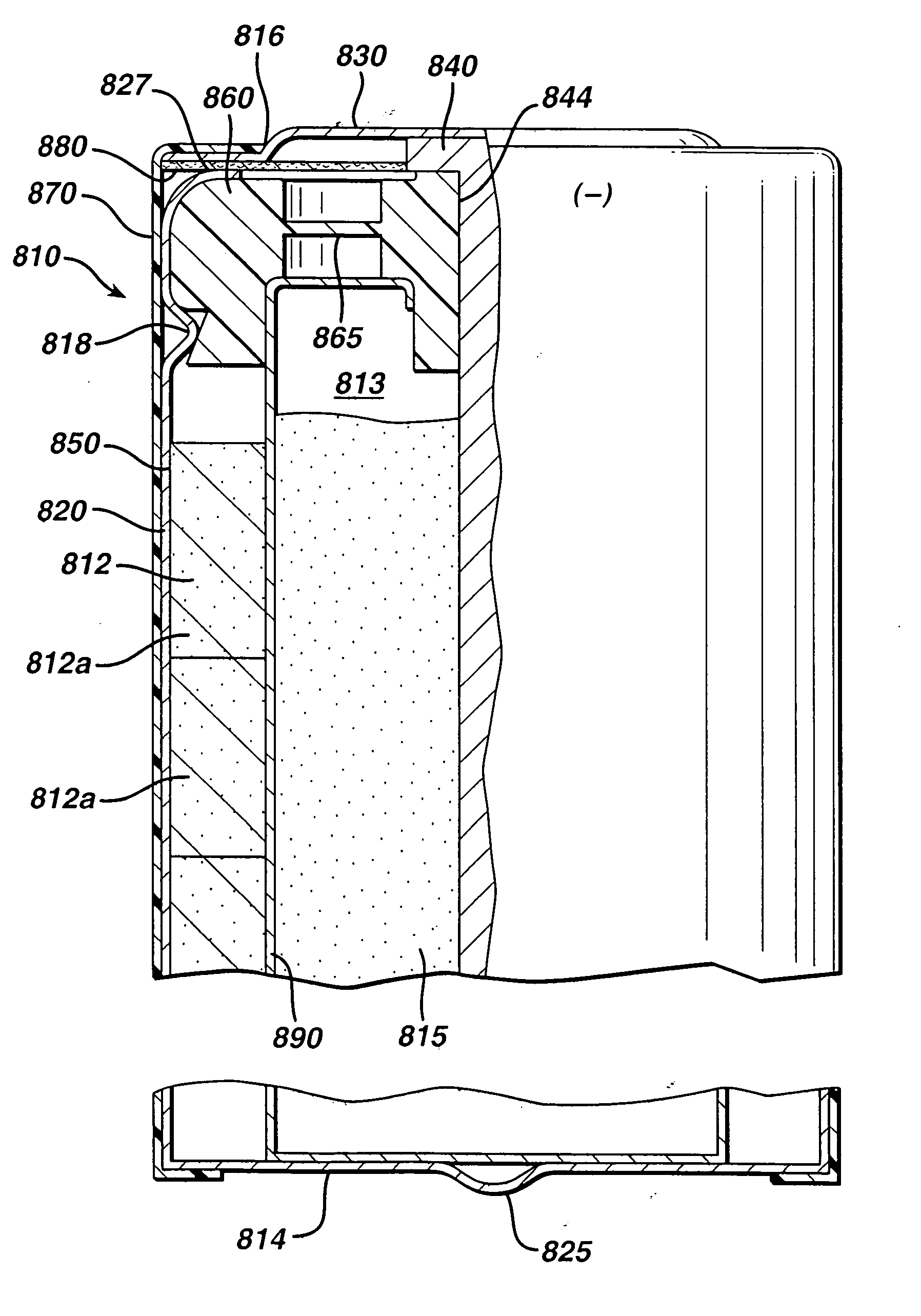
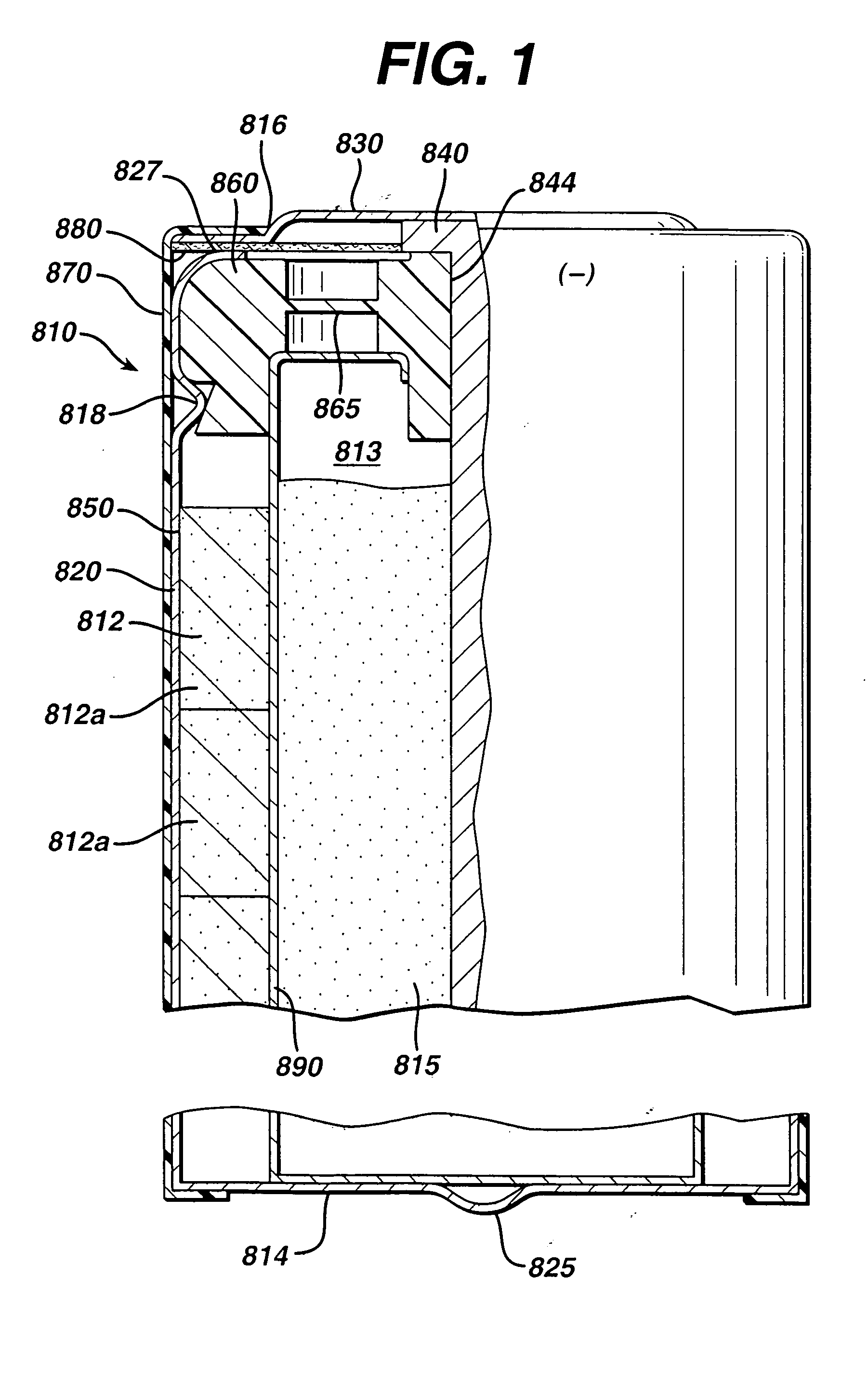
[0050] Test cylindrical AA cells of the general configuration shown in 810 (FIG. 1) were prepared. The cathode 812 in the comparative AA cell and test AA cells, for example, may have the following representative compositions: 80-90 wt % of electrolytic manganese dioxide (e.g., Trona D from Kerr-McGee), 4-10 wt % of expanded graphite (Timcal E-BNB90, BET surface of 24.3 m2 / g ), 5-10 wt % of an aqueous KOH solution having a KOH concentration of about 35-40 wt. %. A specific cathode composition for the comparative AA cell and test AA cells used for the performances tests reported in the Tables was as follows:

Cathode Composition1Wt. %MnO2 (EMD)87Expanded graphite8(Timcal E-BNB90)KOH aqueous5Solution (36 wt %KOH and 2 wt % ZnO)100

Notes:

1Conversion to volume percent can be made using the following real densities: MnO2 (EMD), 4.48 g / cc;

# expanded graphite (Timcal E-BNB90), 2.25 g / cc; and 36 wt % KOH aqueous solution, ...

example 2

Anode from Solid Porous Zinc Mass / Conventional MnO2 Cathode

[0056] Test AA size cells 810 were prepared as in Example 1 except that the anode 815 was formed from the wet zinc mass (wet preform) which was molded into the approximate shape of the anode cavity 813 and then dried to produce the solid porous zinc mass (solid preform) 815C of the invention. The solid preform was inserted into the anode cavity 813 and then aqueous potassium hydroxide electrolyte (concentration between about 35 and 40 wt. % KOH and 2 wt. % ZnO) was added. The solid porous zinc mass (solid preform) immediately absorbed the alkaline electrolyte and expanded to form the final fresh wet anode as described in the description hereinabove. The cathode composition comprising MnO2 was the same as used in Example 1. The cell had 4.6 grams of zinc as in Example 1 and was balanced so that the theoretical capacity of the zinc divided by the theoretical capacity of the MnO2 was about 1.

[0057] The wet zinc mass (wet pre...

example 3

Anode from Solid Porous Zinc Mass / Conventional MnO2 Cathode

[0064] Test AA size cells 810 were prepared as in Example 1 except that the anode 815 was formed from the wet zinc mass (wet preform) which was molded into the approximate shape of the anode cavity 813 and then dried to produce the solid porous zinc mass (solid preform) 815C of the invention. The solid preform was inserted into the anode cavity 813 and then aqueous potassium hydroxide electrolyte (concentration between about 35 and 40 wt. % KOH and 2 wt. % ZnO) was added. The solid porous zinc mass (solid preform) immediately absorbed the alkaline electrolyte and expanded to form the final wet anode as described in the description hereinabove. The cathode composition comprising MnO2 was the same as used in Example 1. The cell had 4.6 grams of zinc as in Example 1 and was balanced so that the theoretical capacity of the zinc divided by the theoretical capacity of the MnO2 was about 1.

[0065] The wet zinc mass (wet preform) h...


PUM

PropertyMeasurementUnit
Lengthaaaaaaaaaa
Lengthaaaaaaaaaa
Lengthaaaaaaaaaa

Abstract

A method of forming an anode comprising zinc for an alkaline cell. The method involves mixing zinc particles with binders including preferably polyvinylalcohol, surfactant and water to form a wet paste. The wet paste is molded into the near shape of the cell's anode cavity and then heated to evaporate water. A solid porous zinc mass is formed having microscopic void spaces between the zinc particles. The solid mass can be inserted into the cell's anode cavity and aqueous alkaline electrolyte, preferably comprising potassium hydroxide, then added. The solid mass absorbs the aqueous electrolyte and expands to fill the anode cavity to form the final fresh anode. Zinc fibers may be added to increase the structural integrity of the solid mass.

Description

CROSS REFERENCE TO RELATED APPLICATIONS [0001] This application is a continuation in part of application Ser. No. 10 / 613,686, filed Jul. 3, 2003.FIELD OF THE INVENTION [0002] This invention relates to zinc anode for an alkaline cell. The invention relates to an anode prepared by preforming a solid porous mass comprising zinc particles to which aqueous alkaline electrolyte is added to form the final anode. The invention relates to adding strands of zinc fibers to the anode. BACKGROUND OF THE INVENTION [0003] Conventional alkaline electrochemical cells have an anode comprising zinc and a cathode comprising manganese dioxide. The cell is typically formed of a cylindrical casing, but casings having flat surfaces or disk type button cells are also possible. The casing is initially formed with an enlarged open end and opposing closed end. After the cell contents are supplied, an end cap with insulating plug is inserted into the open end. The cell is closed usually by crimping the casing e...

Claims


Application Information

Patent Timeline
IPC IPC(8): H01M4/02H01M4/24H01M4/62H01M10/24H01M10/26
CPCH01M2/1673H01M4/02H01M4/244H01M4/26H01M4/621H01M4/622Y10T29/49108H01M6/06H01M10/24H01M10/26H01M2004/027Y02E60/124Y10T29/49115H01M6/04H01M50/46Y02E60/10
Inventor RICHARDS, THOMAS C.CINTRA, GEORGEGILICINSKI, ANDREW G.JIANG, ZHIPINGPARENT, C. ROBERT
Owner DURACELL U S OPERATIONS
Why Eureka
Try Eureka