
Assembler capable of reducing size of object code, and processor for executing the object code

a technology of object code and processor, applied in the field of assembly capable of reducing the size of object code, can solve the problems of deterioration in performance, automatic inserting of unnecessary nop instructions, etc., and achieve the effect of reducing the size of an object cod

Inactive Publication Date: 2005-05-19
RENESAS TECH CORP
View PDF28 Cites 7 Cited by
  • Summary
  • Abstract
  • Description
  • Claims
  • Application Information

AI Technical Summary

Benefits of technology

[0009] An object of the present invention is to provide an assembler capable of reducing the size of an object code.
[0010] Another object of the present invention is to provide a processor in which an unnecessary NOP instruction is prevented from being inserted.
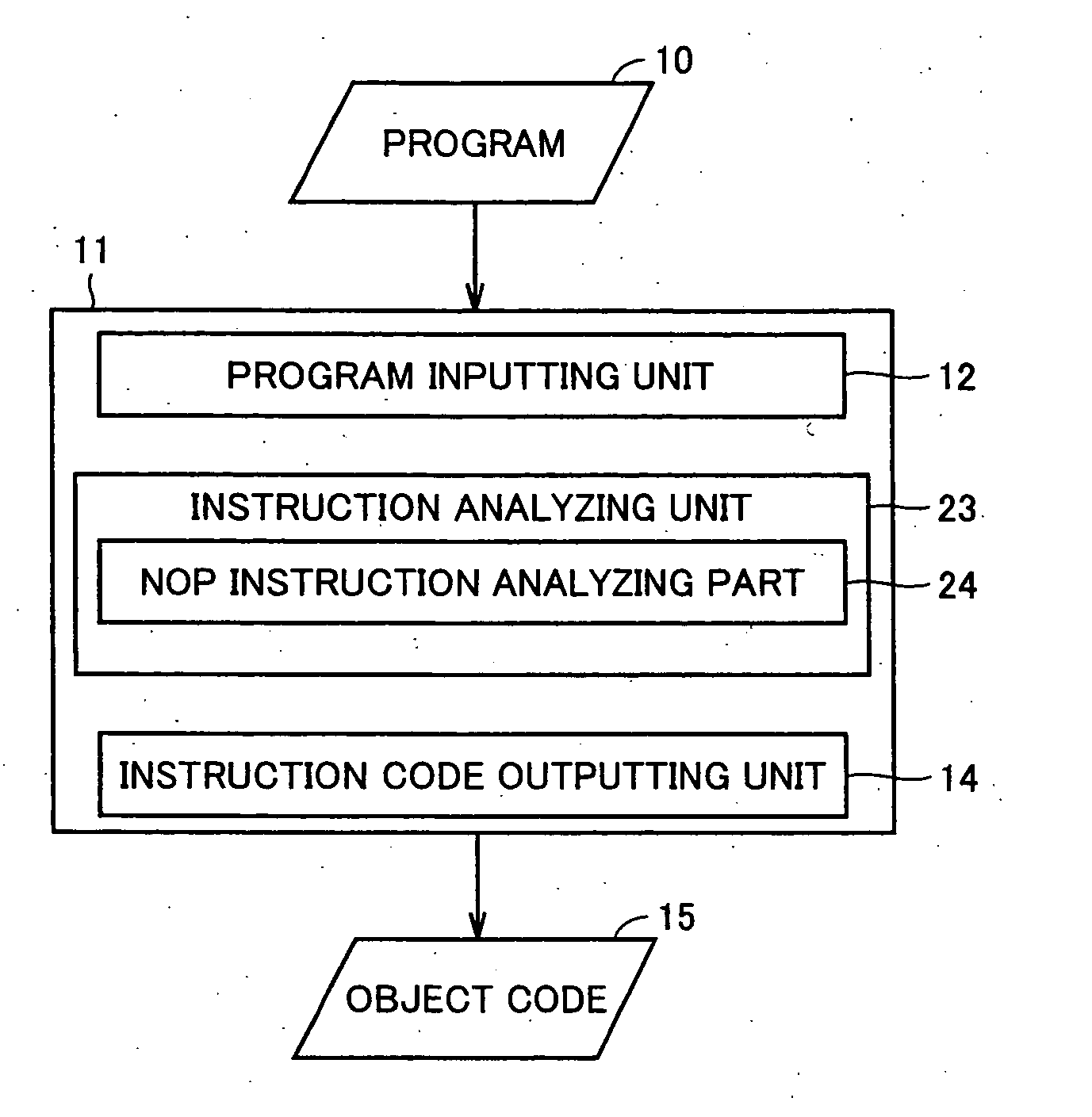
[0012] Since the instruction analyzing unit sequentially analyzes instructions of an inputted program and encodes continuous no-operation instructions as one continuous no-operation instruction, the size of the object code can be reduced.
[0014] When a decoded instruction is a continuous no operation instruction, in the case where the instruction fetched immediately before the continuous no-operation instruction is a branch instruction and a branch condition is satisfied, the instruction decoding unit processes the continuous no-operation instruction as a normal no-operation instruction. Consequently, insertion of an unnecessary no-operation instruction can be prevented.
[0016] When the decoded instruction is a branch instruction with no operation and a branch condition is satisfied, the instruction decoding unit inserts a no-operation instruction. When the decoded instruction is a branch instruction with no operation and a branch condition is not satisfied, the instruction decoding unit does not insert a no-operation instruction. Thus, insertion of an unnecessary no-operation instruction can be prevented.

Problems solved by technology

Therefore, when the continuous NOP instruction is executed in the case where a branch condition of the branch instruction is satisfied, an unnecessary NOP is executed, and it causes a problem of deterioration in performance.
Consequently, there is a problem in that an unnecessary NOP instruction is automatically inserted also in the case where the branching condition is not satisfied.

Method used


Image

  • Assembler capable of reducing size of object code, and processor for executing the object code
  • Assembler capable of reducing size of object code, and processor for executing the object code
  • Assembler capable of reducing size of object code, and processor for executing the object code

Examples


first embodiment

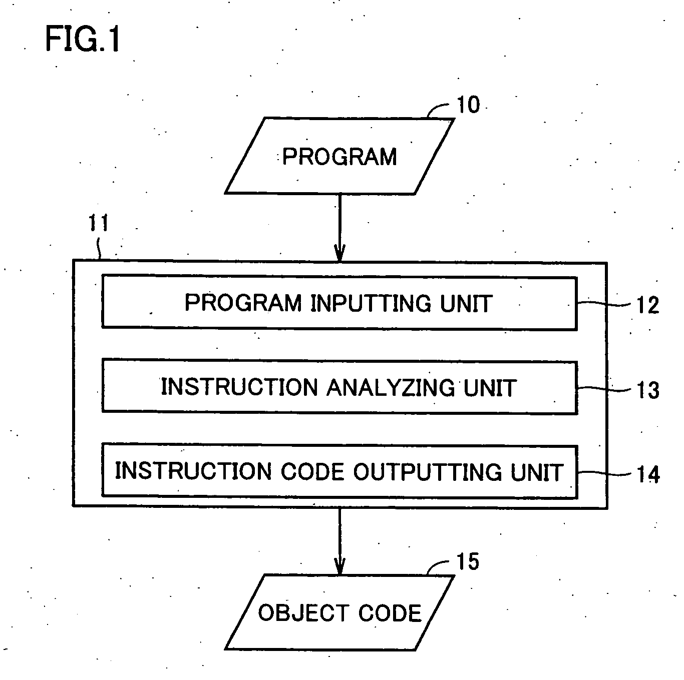
[0041] First, an operation of a general assembler will be described. FIG. 1 is a block diagram showing a functional configuration of a general assembler. An assembler 111 includes a program inputting unit 12 to which a program 10 described in a mnemonic code is inputted, an instruction analyzing unit 13 for analyzing instruction codes of the program inputted to the program inputting unit 12 one by one and outputting an encoded instruction, and an instruction code outputting unit 14 for outputting the encoded instruction which is outputted from instruction analyzing unit 13 as an object code 15.

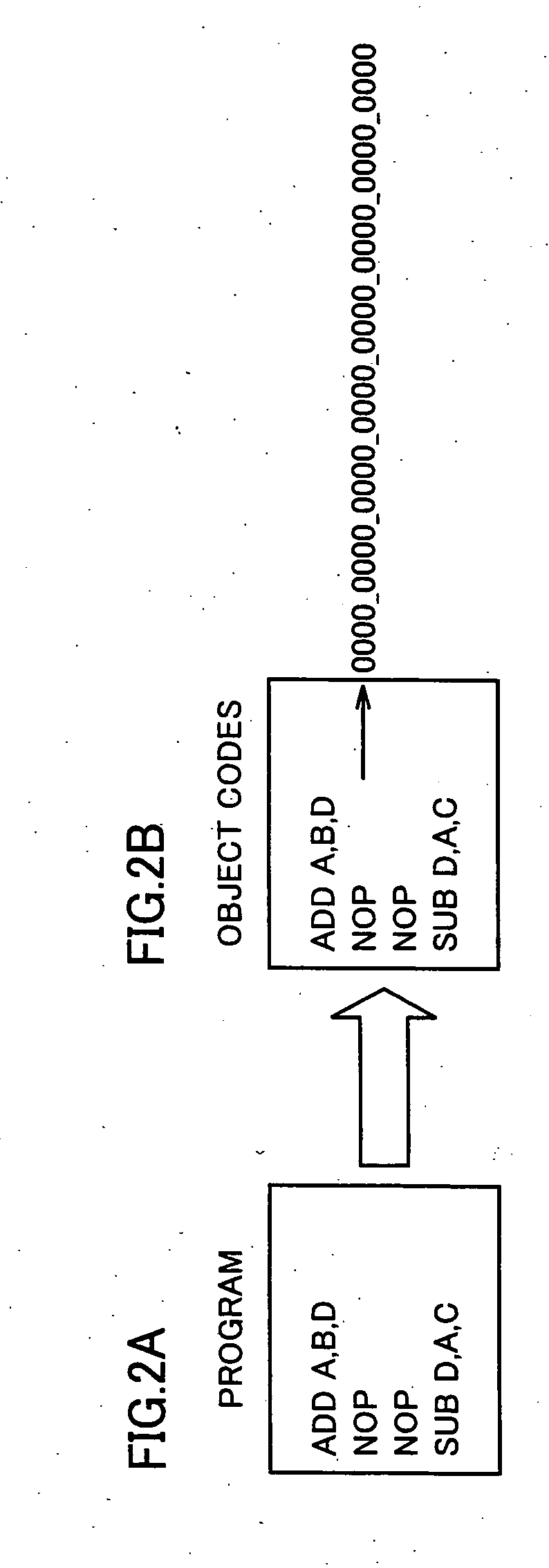
[0042]FIGS. 2A and 2B are diagrams showing an example of a program which is inputted to the assembler shown in FIG. 1, and generated object codes. When the program shown in FIG. 2A is inputted to program inputting unit 12, instruction analyzing unit 13 analyzes instructions of the program shown in FIG. 2A one by one and outputs encoded instructions. As a result, instruction code outputting un...

second embodiment

[0073] A configuration example of an assembler in a second embodiment of the present invention is similar to that of the assembler in the first embodiment of the present invention shown in FIG. 3. A functional configuration of the assembler in the second embodiment of the present invention is similar to that of the assembler in the first embodiment of the present invention shown in FIG. 4. Therefore, detailed description of the same configurations and functions will not be repeated here.

[0074]FIG. 9 is a flowchart for describing a procedure of the assembler in the second embodiment of the present invention. The procedure is different from that of the assembler in the first embodiment of the present invention shown in FIG. 5 only with respect to the point that step S3 is replaced with step S13. Therefore, detailed description of the same procedure will not be repeated here.

[0075] In step S13, NOP instruction analyzing part 24 determines whether the NOP instruction is a labeled NOP ...

third embodiment

[0086]FIG. 11 is a block diagram showing a schematic configuration of a processor in a third embodiment of the present invention. The processor includes a program address generating unit 30 for generating an address of an instruction to be fetched, an instruction fetching unit 31 for fetching an instruction in accordance with the address generated by program address generating unit 30, an instruction decoding unit 32 for decoding the instruction fetched by instruction fetching unit 31, a data reading unit 33 for reading data from a memory or a register in accordance with a result of decoding by instruction decoding unit 32, an operation processing unit 34 for performing an integer arithmetic operation, a floating point arithmetic operation and the like by using the data read by data reading unit 33 as a source, and a data writing unit 35 for writing a result of the operation performed by operation processing unit 34 into a memory or a register.

[0087] Program address generating unit...


PUM


Abstract

An instruction analyzing unit sequentially analyzes instructions of a program which is inputted to a program inputting unit. A NOP instruction analyzing part encodes continuous NOP instructions as one continuous NOP instruction. An instruction code outputting unit outputs the instruction encoded by the instruction analyzing unit as an object code. Therefore, the size of the object code can be reduced.

Description

BACKGROUND OF THE INVENTION [0001] 1. Field of the Invention [0002] The present invention relates to an assembler for converting a program described in a mnemonic code into an object code of a machine language and a processor for executing the object code and, more particularly, to an assembler capable of reducing the size of an object code and a processor for executing the object code. [0003] 2. Description of the Background Art [0004] In a program control type processor core, in the case where a plurality of cycles are necessary to complete execution of instructions such as a load instruction, a branch instruction and an operation instruction, wait time occurs. In order to execute an instruction of using results of the instructions, it is necessary to insert a NOP instruction to guarantee accurate execution of a program. Related techniques include the inventions disclosed in Japanese Patent Laying-Open Nos. 4-275603 and 2-12429. [0005] In a programmable controller disclosed in Jap...

Claims


Application Information

Patent Timeline
IPC IPC(8): G06F9/45
CPCG06F8/4434
Inventor KOBARA, JUNKOKAWAI, HIROYUKIMORINAKA, HIROYUKIINOUE, YOSHITSUGU
Owner RENESAS TECH CORP
Learn More