
Polymer post insulator apparatus

Inactive Publication Date: 2005-05-26
NGK INSULATORS LTD
View PDF9 Cites 2 Cited by
  • Summary
  • Abstract
  • Description
  • Claims
  • Application Information

AI Technical Summary

Benefits of technology

[0016] According to the above-described construction, the strength in the vertical direction in particular can be improved in the present invention. Of course, it goes without saying that, by arranging the polymer post insulators in parallel in an arbitrary direction other than the vertical direction and connecting two ends thereof, the strength in an arbitrary direction can be greatly improved. Also, the strength in a direction other than the direction of parallel arrangement can be improved as compared with the strength of a single polymer post insulator, though the improvement is not so great as in the direction of parallel arrangement.
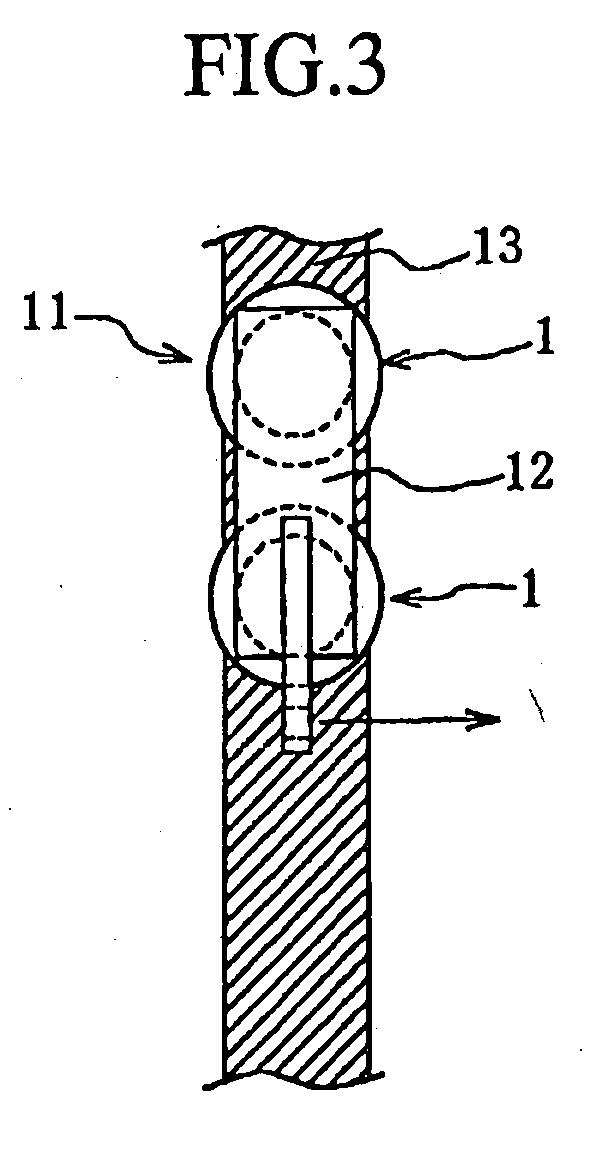
[0018] Further, since it is clear that the weight of the electric power transmission line acts in the vertical direction, it is preferable that, in mounting the polymer insulator apparatus in the horizontal direction onto the supporting structure, the plurality of polymer post insulators are arranged in parallel in the vertical direction, and the two ends thereof are connected. By doing so, the polymer insulator apparatus of the present invention can exhibit the maximum performance.

Problems solved by technology

This restricts the load that can be supported in a high-voltage transmission line that requires a long insulating distance.
This may restrict the range of application as a line post because it may give fears to inhabitants around the electric power transmission line path even though no problem is raised concerning its strength.
For these reasons, application of the line post constituted with polymer post insulators alone is not so much developed for high-voltage electric power transmission lines exceeding 161 kV that require an especially longer insulator length.
Further, both of the reinforced structures are a one-directional reinforced structure regarding the load in the vertical direction, so that they do not provide reinforcement against the load generated in the longitudinal direction due to conductor breaking, uneven wind to the line, snow falls, and the like, or the load temporarily generated in the longitudinal direction at a time of construction of a transmission line.
This raises a problem in that, unless suitable consideration is given to the transmission line path and apparatus design, the apparatus will whirl and swivel like dominoes by a load in the longitudinal direction that may possibly be generated in a normal state.
However, this requires a large placement surface, so that the apparatus can be applied only to a supporting structure such as a steel tower having sufficient width and height, and cannot be mounted onto a supporting structure constructed by one pole such as a steel pole or wood pole.
However, as compared with a insulator apparatus without having a middle connection metal fitting piece part, the apparatus increases the costs due to increase in the number of components, in the difficulty of assembling, and in the number of production processes.
This raises a problem of increase in the electric power transmission line path width as well.

Method used


Image

  • Polymer post insulator apparatus
  • Polymer post insulator apparatus
  • Polymer post insulator apparatus

Examples


Embodiment Construction

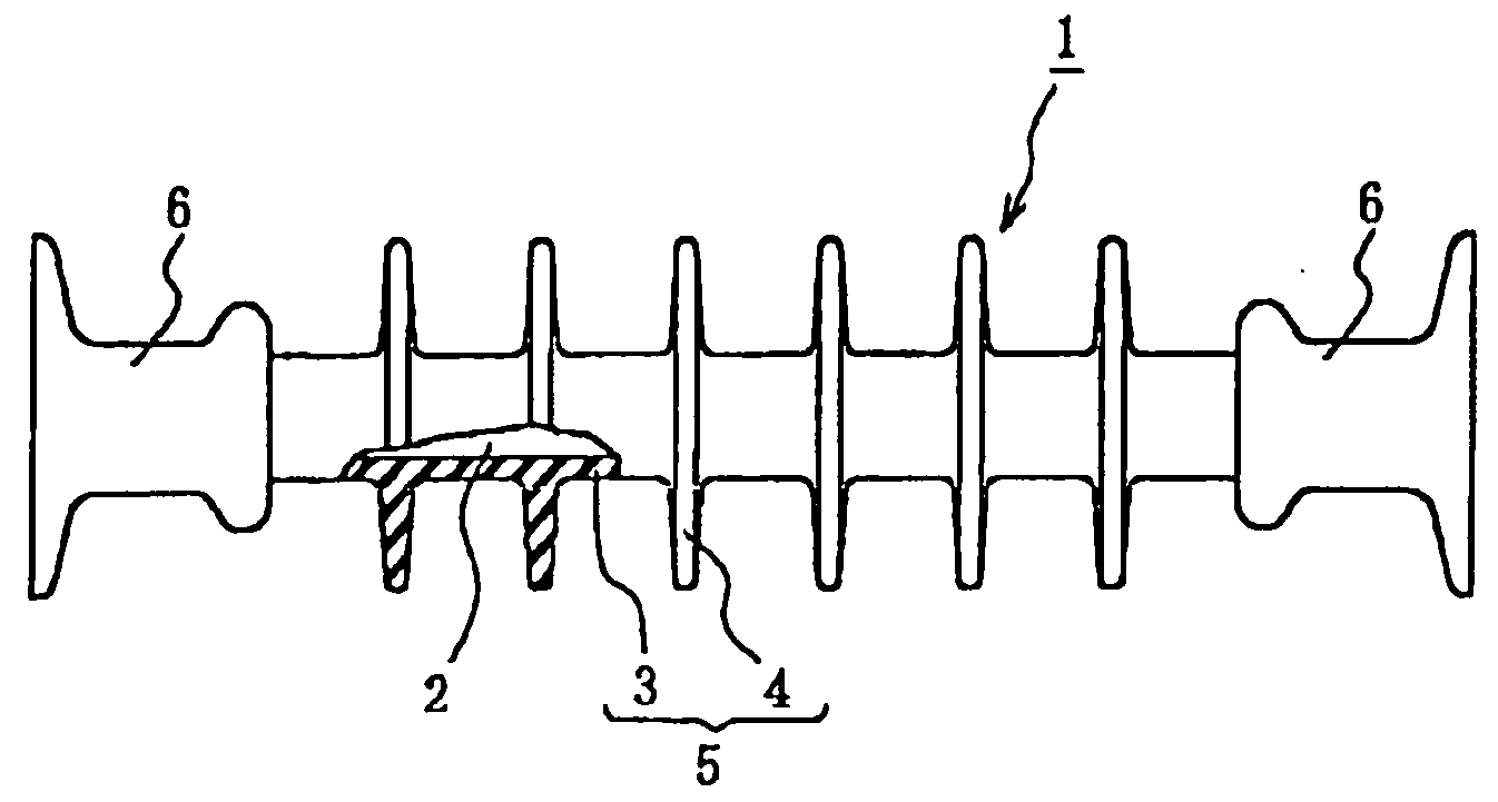
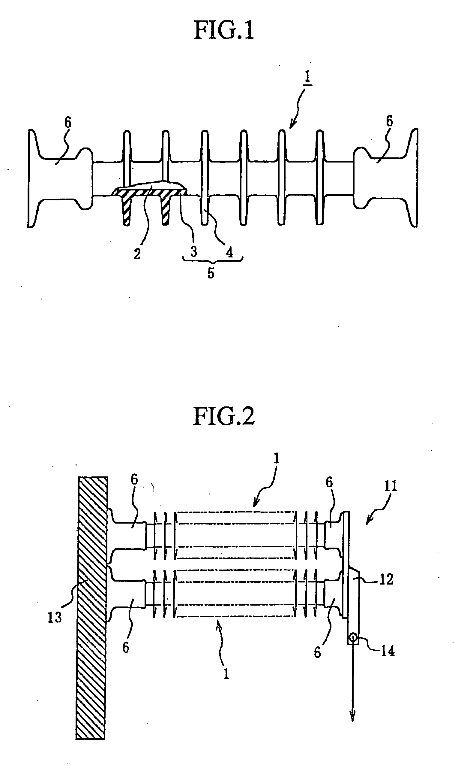
[0022]FIG. 1 is a view showing one construction example of a polymer post insulator constituting a polymer insulator apparatus according to the present invention. In the example shown in FIG. 1, a polymer post insulator 1 is constituted with a core member 2, an outer cover 5 made of a sheath 3 and sheds 4 disposed around core member 2, and holding fitting metal pieces 6 disposed at two ends of core member 2. Further, core member 2 is made of, for example, a solid FRP, and outer cover 5 made of sheath 3 and sheds 4 is made of, for example, silicone rubber. Also, an end of holding metal fitting piece 6 has a flange shape, and is constituted to be capable of being fixed onto a planar plate member or the like with screws. The construction of this polymer post insulator is the same as in the prior art.

[0023]FIG. 2 is a view showing one example of a polymer insulator apparatus according to the present invention. In the example shown in FIG. 2, a polymer insulator apparatus 11 according t...


PUM


Abstract

A polymer insulator apparatus having a rectangular structure including plural polymer post insulators, a supporting structure and a plate member, wherein a first end of each polymer post insulator is connected to the supporting structure, and a second end of each said plural post insulator is connected to the plate member. When an axial direction along a length of each plural polymer post insulator is substantially a horizontal direction and an axial direction along a length of the supporting structure is substantially a vertical direction, the plural polymer post insulators support a weight of a load acting in the vertical direction.

Description

REFERENCE TO RELATED APPLICATION [0001] This application claims priority from Japanese Application 2002-340939 filed Nov. 25, 2002, the entireties of which is incorporated herein by reference. BACKGROUND OF THE INVENTION [0002] 1. Field of the Invention [0003] The present invention relates to a construction of a polymer insulator apparatus that is mounted in the horizontal direction onto a supporting structure for electric power transmission line path, such as a steel pole, a wood pole, or a steel tower, as well as to a method of mounting the same. [0004] 2. Description of the Background Art [0005] A method of applying insulators in which a post insulator is mounted in the horizontal direction onto a supporting structure and a conductor is supported at one end thereof via a suitable connection metal fitting piece, i.e. a so-called line post, is widely applied as a method of compactifying an electric power transmission line path. In recent years, there is an increasing number of exam...

Claims


Application Information

Patent Timeline
IPC IPC(8): H01B17/16
CPCH01B17/16
Inventor FUJII, SHUJI
Owner NGK INSULATORS LTD
Learn More