Doubly asymmetric double gate transistor structure

a double gate transistor and asymmetric technology, applied in the direction of transistors, semiconductor devices, electrical equipment, etc., can solve the problems of affecting the reliability of the transistor, the design and fabrication and the reliability of the double gated cmos transistor is difficult to ensure. the effect of reliability and minimum feature siz

Inactive Publication Date: 2005-05-26
INT BUSINESS MASCH CORP
View PDF7 Cites 31 Cited by
  • Summary
  • Abstract
  • Description
  • Claims
  • Application Information

AI Technical Summary

Problems solved by technology

FETs are used in almost all types of integrated circuit design (i.e., microprocessors, memory, etc.) Unfortunately, increased device density in CMOS FET can result in degradation of performance and / or reliability.
Unfortunately, several difficulties arise in the design and fabrication of double gated CMOS transistors.
First, the relative dimensions of a double gated transistor are such that it is difficult to reliably fabricate one that has a reliable performance and minimum feature size.
In particular, current fabrication techniques have generally resulted in a double gated transistor that has either too high a threshold voltage, or too low of a threshold voltage.

Method used


Image

  • Doubly asymmetric double gate transistor structure
  • Doubly asymmetric double gate transistor structure
  • Doubly asymmetric double gate transistor structure

Examples


Embodiment Construction

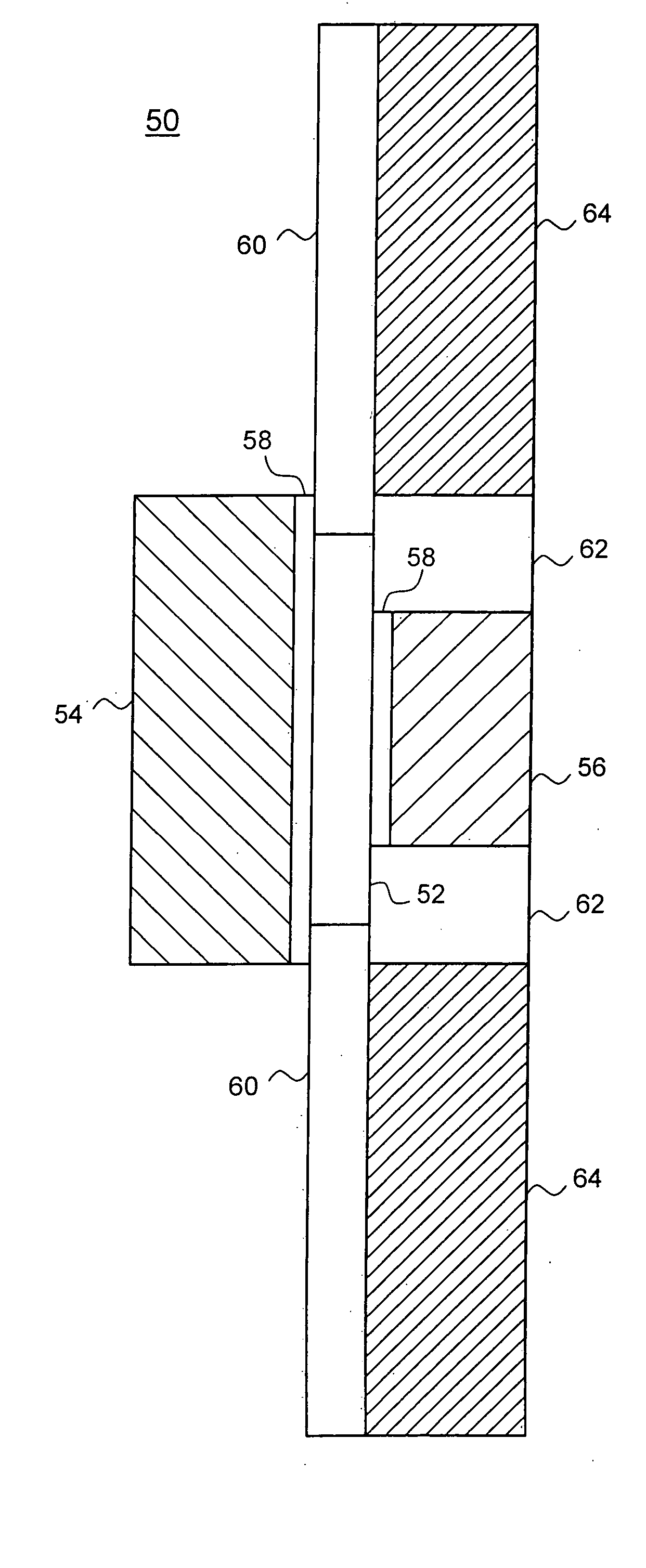
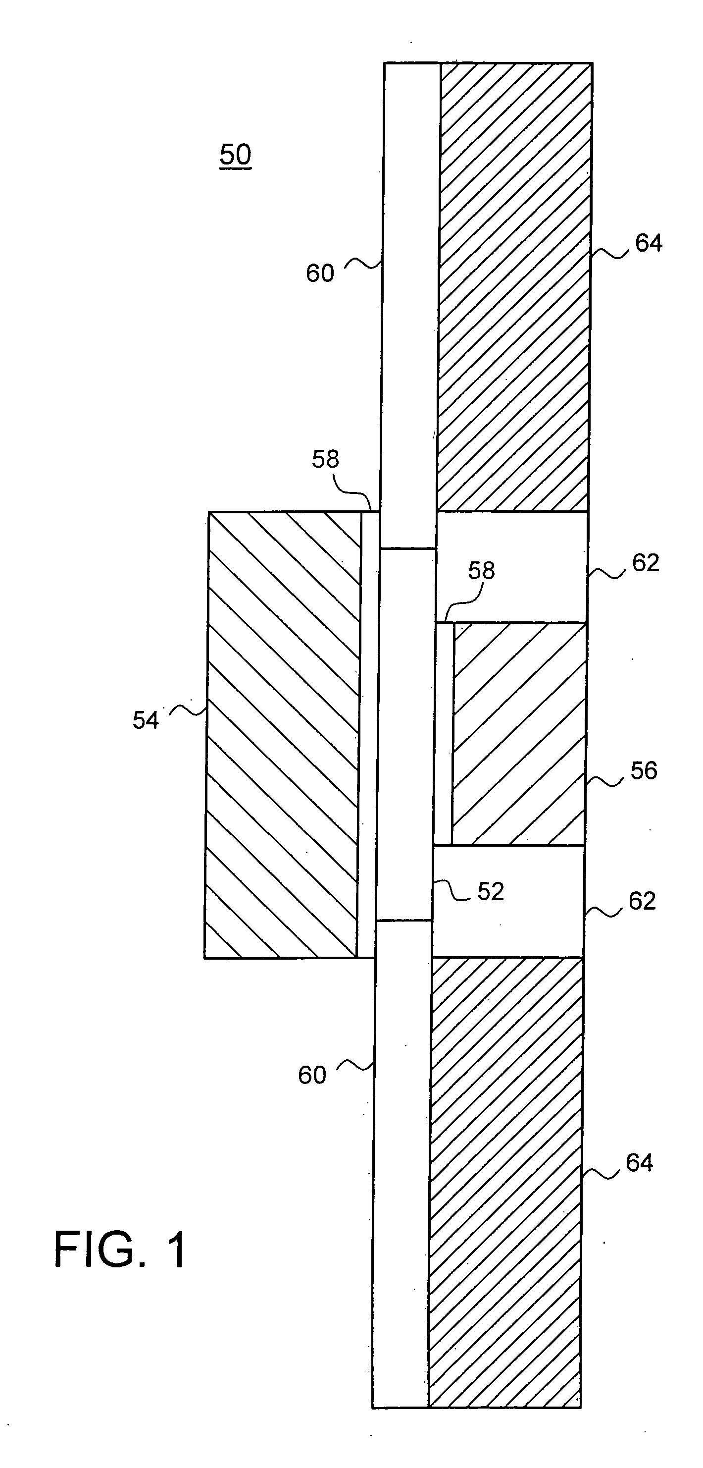
[0023] Accordingly, the present invention provides a double gated transistor and a method for forming the same that results in improved device performance and density. The preferred embodiment of the present invention provides a double gated transistor with asymmetric gate doping, where one of the double gates is doped degenerately n-type and the other degenerately p-type. By doping one of the gates n-type, and the other p-type, the threshold voltage of the resulting device is improved. In particular, by asymmetrically doping the two gates, the resulting transistor can, with adequate doping of the body, have a threshold voltage in a range that enables low-voltage CMOS operation. For example, a transistor can be created that has a threshold voltage between 0V and 0.5V for nFETs and between 0 and −0.5V for pFETs.

[0024] Additionally, the preferred transistor design uses an asymmetric structure that results in reduced gate-to-drain and gate-to-source capacitance. In particular, dimensi...


PUM


Abstract

The present invention provides a double gated transistor and a method for forming the same that results in improved device performance and density. The preferred embodiment of the present invention provides a double gated transistor with asymmetric gate doping, where one of the double gates is doped degenerately n-type and the other degenerately p-type. By doping one of the gates n-type, and the other p-type, the threshold voltage of the resulting device is improved. Additionally, the preferred transistor design uses an asymmetric structure that results in reduced gate-to-drain and gate-to-source capacitance. In particular, dimensions of the weak gate, the gate that has a workfunction less attractive to the channel carriers, are reduced such that the weak gate does not overlap the source / drain regions of the transistor. In contrast the strong gate, the gate having a workfunction that causes the inversion layer to form adjacent to it, is formed to slightly overlap the source / drain regions. This asymmetric structure allows for the performance benefits of a double gate design without the increased capacitance that would normally result.

Description

CROSS REFERENCE TO RELATED APPLICATIONS [0001] Reference is made to co-pending U.S. Patent Application Attorney Reference BUR920010171 US 1, entitled “Implated Assymetric Doped Polysilicon Gate FinFET.”BACKGROUND OF THE INVENTION [0002] The present invention relates generally to the field of semiconductor manufacturing and, more specifically, to a method for forming double gated field effect transistors. [0003] The need to remain cost and performance competitive in the production of semiconductor devices has caused continually increasing device density in integrated circuits. To facilitate the increase in device density, new technologies are constantly needed to allow the feature size of these semiconductor devices to be reduced. [0004] The push for ever increasing device densities is particularly strong in CMOS technologies, such as the in the design and fabrication of field effect transistors (FETs). FETs are used in almost all types of integrated circuit design (i.e., microproces...

Claims


Application Information

Patent Timeline
Patent Type & Authority Applications(United States)
IPC IPC(8): H01L21/336H01L29/786
CPCH01L29/66795H01L29/78636H01L29/785
Inventor NOWAK, EDWARD J.
Owner INT BUSINESS MASCH CORP
Why Eureka
Try Eureka