Vehicle brake system with active hydraulic brake force reinforcement

a brake force reinforcement and brake system technology, applied in the direction of brake systems, vehicle components, transportation and packaging, etc., to achieve the effect of reliable brake force adjustmen

Inactive Publication Date: 2005-05-26
CONTINENTAL TEVES AG & CO OHG
View PDF6 Cites 15 Cited by
  • Summary
  • Abstract
  • Description
  • Claims
  • Application Information

AI Technical Summary

Benefits of technology

[0006] In view of the above, an object of the invention is to overcome the shortcomings of hydraulic brake force boosting and provide a reliable brake force adjustment. It is desired that even relatively insignificant changes of the driver's pedal force will cause corresponding changes of the brake pressure or the vehicle deceleration.

Problems solved by technology

Systems with additional hydraulic brake force boosting referred to hereinabove which operate with valves for pressure control and pumps for pressure generation suffer from a system-inherent problem of realizing analog brake force boosting because there is only a stepwise pressure increase due to valve switching operations or pump operations.

Method used


Image

  • Vehicle brake system with active hydraulic brake force reinforcement
  • Vehicle brake system with active hydraulic brake force reinforcement
  • Vehicle brake system with active hydraulic brake force reinforcement

Examples


Embodiment Construction

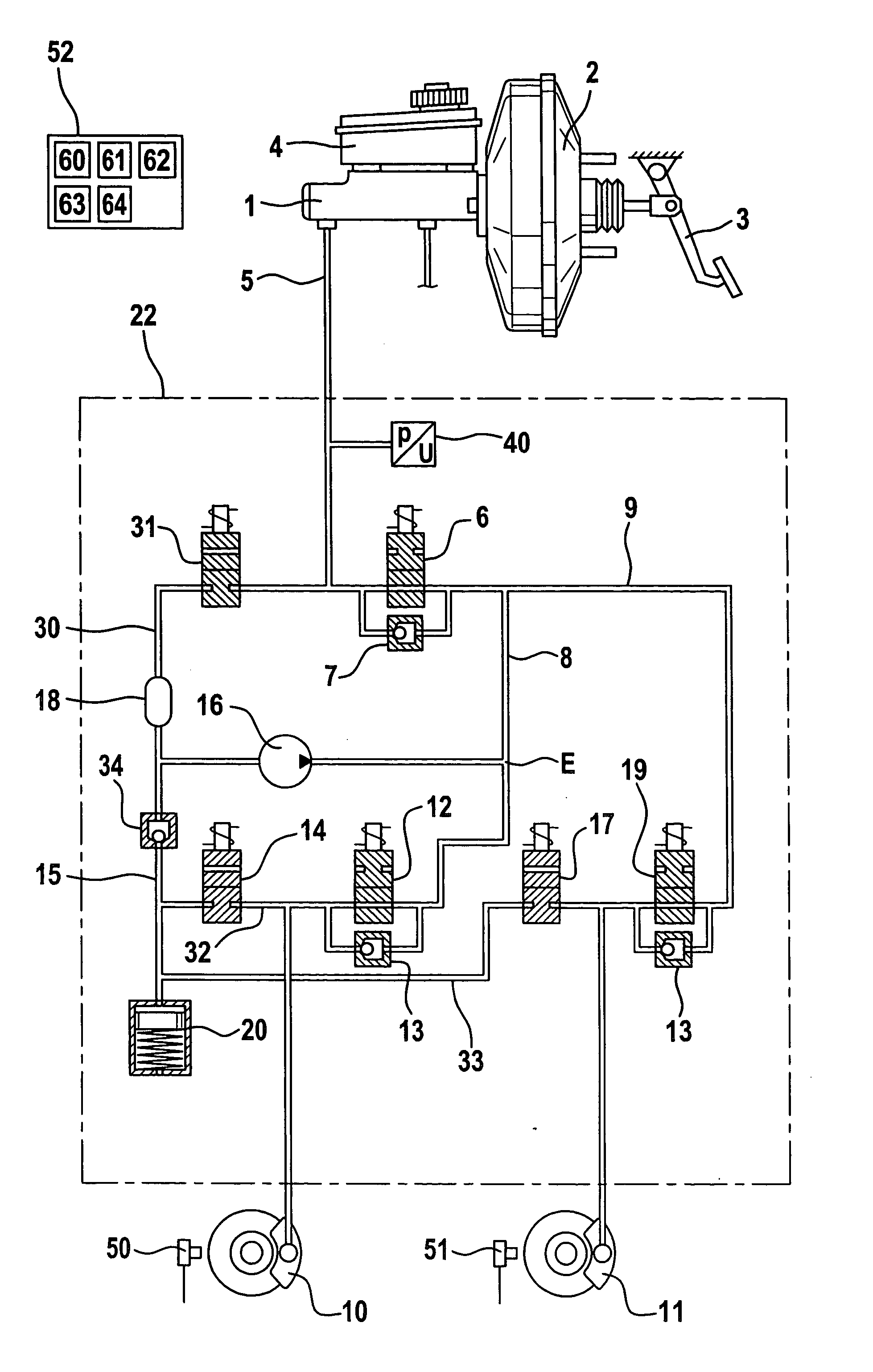
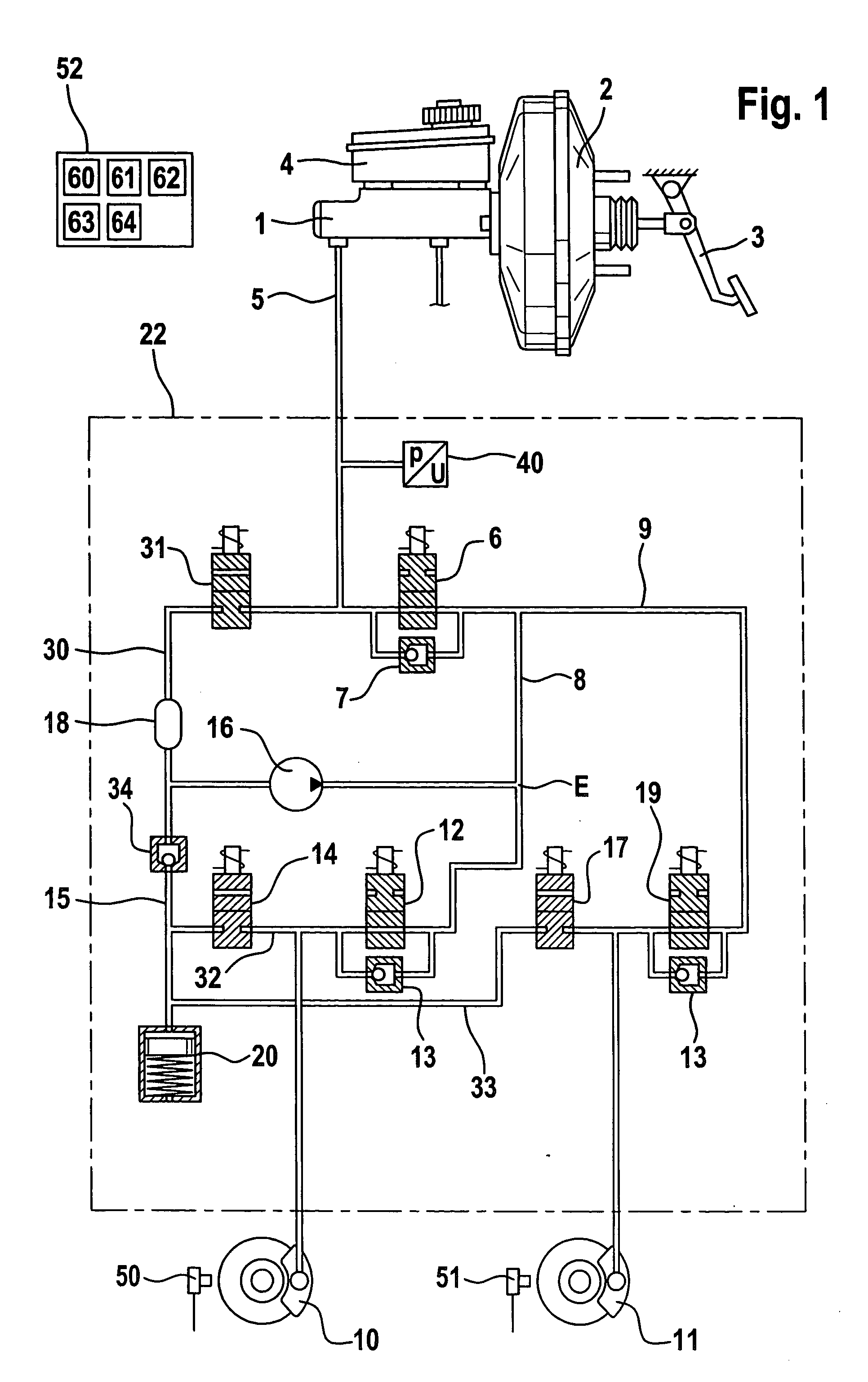
[0036] The dual-circuit brake system for motor vehicles, as illustrated in FIG. 1, is composed of an actuating unit 1, e.g. a brake cylinder, with a brake booster 2 actuated by a brake pedal 3. Arranged at the actuating unit 1 is a supply reservoir 4 that contains a pressure fluid volume and is connected to the working chamber of the actuating unit in the position of brake release. The one brake circuit illustrated comprises a brake line 5 that is connected to a working chamber of the actuating unit 1 and provides a connection between the actuating unit 1 and the one hydraulic unit 22. The brake line 5 includes a separating valve 6 providing an open passage for the brake line 5 in the inactive position of the separating valve 6. Connected in parallel to the separating valve 6 is a non-return valve 7 that opens in the direction of the wheel brakes 10, 11. The separating valve performs the function of a pressure-limiting valve. The separating valve is herein used as a pressure modulat...


PUM


Abstract

The present invention relates to a method and a device for controlling a vehicle brake system with active hydraulic brake force boosting. In this method, an active pressure-increasing unit and/or a pressure modulation unit is actuated according to a comparison between a nominal pressure or a nominal vehicle speed or quantities derived therefrom, in particular a nominal vehicle acceleration, and an actual pressure or an actual vehicle speed or quantities derived therefrom, in particular an actual vehicle acceleration.

Description

TECHNICAL FIELD [0001] The present invention relates to a method for controlling a vehicle brake system with active hydraulic brake force boosting. [0002] The invention likewise relates to a device for controlling a vehicle brake system with active hydraulic brake force boosting, with an actuating unit by means of which the driver can introduce brake pressure into a hydraulic unit, with at least one wheel brake that is connected to the actuating unit by way of the hydraulic unit comprising at least one brake line, with a pump communicating with its suction side with the actuating unit by way of a change-over valve and communicating with its pressure side with the brake line, with an actuatable inlet valve arranged in the brake line, with an actuatable separating valve interposed between the inlet valve and the actuating unit, with an actuatable outlet valve arranged in a return line, with a pressure sensor associated with the actuating unit, with a wheel speed sensor and with a firs...

Claims


Application Information

Patent Timeline
Patent Type & Authority Applications(United States)
IPC IPC(8): B60T8/44B60T8/48B60T13/20B60T13/52B60T13/58B60T13/66B60T13/68B60T17/02
CPCB60T8/442B60T13/20B60T13/52B60T13/581B60T13/662B60W2720/106B60T17/02B60T2201/03B60W2510/182B60W2520/10B60W2710/182B60T13/686
Inventor GRONAU, RALPHREVIOL, RALFWOYWOD, JURGEN
Owner CONTINENTAL TEVES AG & CO OHG
Why Eureka
Try Eureka