Eureka AIR delivers breakthrough ideas for toughest innovation challenges, trusted by R&D personnel around the world.

Motor

Inactive Publication Date: 2005-05-26
NIDEC SANKYO CORP
View PDF5 Cites 7 Cited by
  • Summary
  • Abstract
  • Description
  • Claims
  • Application Information

AI Technical Summary

Benefits of technology

[0018] It is an object of the present invention to provide a motor that can improve the bonding strength and perpendicularity of permanent magnets with respect to a rotation shaft of the motor, while maintaining the required rotation performance, thinness and compactness of the motor.

Problems solved by technology

The reduction in bonding areas leads to problems in that a sufficient bonding force cannot obtained between the first and second permanent magnets 56 and 57 and the rotation shaft 55, and the required perpendicularity of the first and second permanent magnets 56 and 57 with respect to the rotation shaft 55 cannot be obtained.
Consequently, variations are caused in the magnetic attraction force and magnetic repelling force between the first and second permanent magnets 56 and 57 and their opposing pole teeth 521a and 523a, and 531a and 533a, which results in problems of irregular rotation speed and deteriorated rotation performance of the motor 50.
Accordingly, although the adhesive retaining concave section 57a that enhances the bonding force is formed, it is difficult to obtain a sufficient bonding force or a required perpendicularity.
Due to the physical property of the mixture, its flow ability is poor, and therefore a problem arises in that a metal mold having a complex shape cannot be completely filled with the mixture, and it is difficult for the press machine to apply a uniform pressure to areas formed in the concave section.
However, this method leads to problems of an increased number of manufacturing steps and a higher cost.

Method used


Image

  • Motor
  • Motor
  • Motor

Examples


Embodiment Construction

[0033] Motors in accordance with embodiments of the present invention are described below with reference to the accompanying drawings.

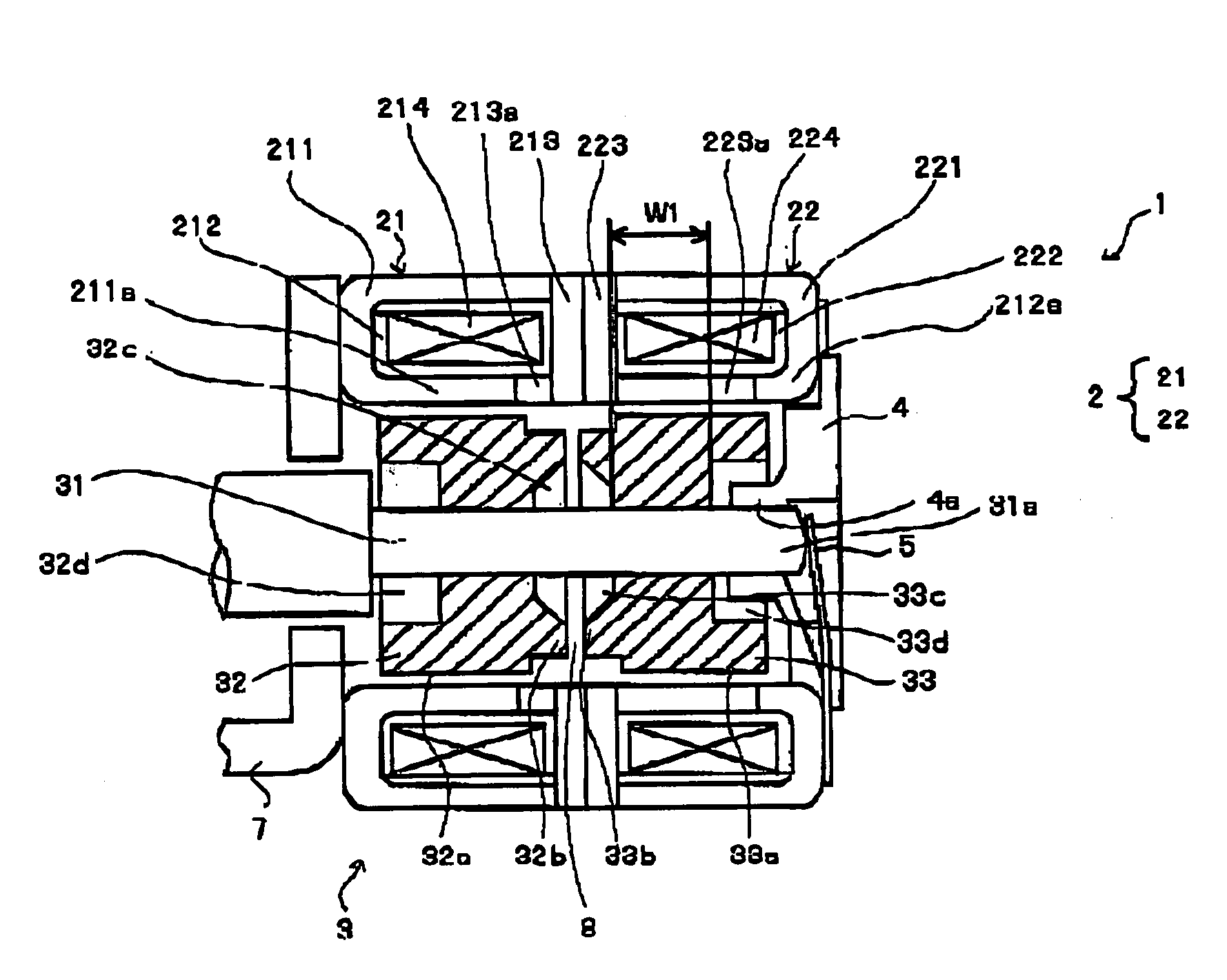
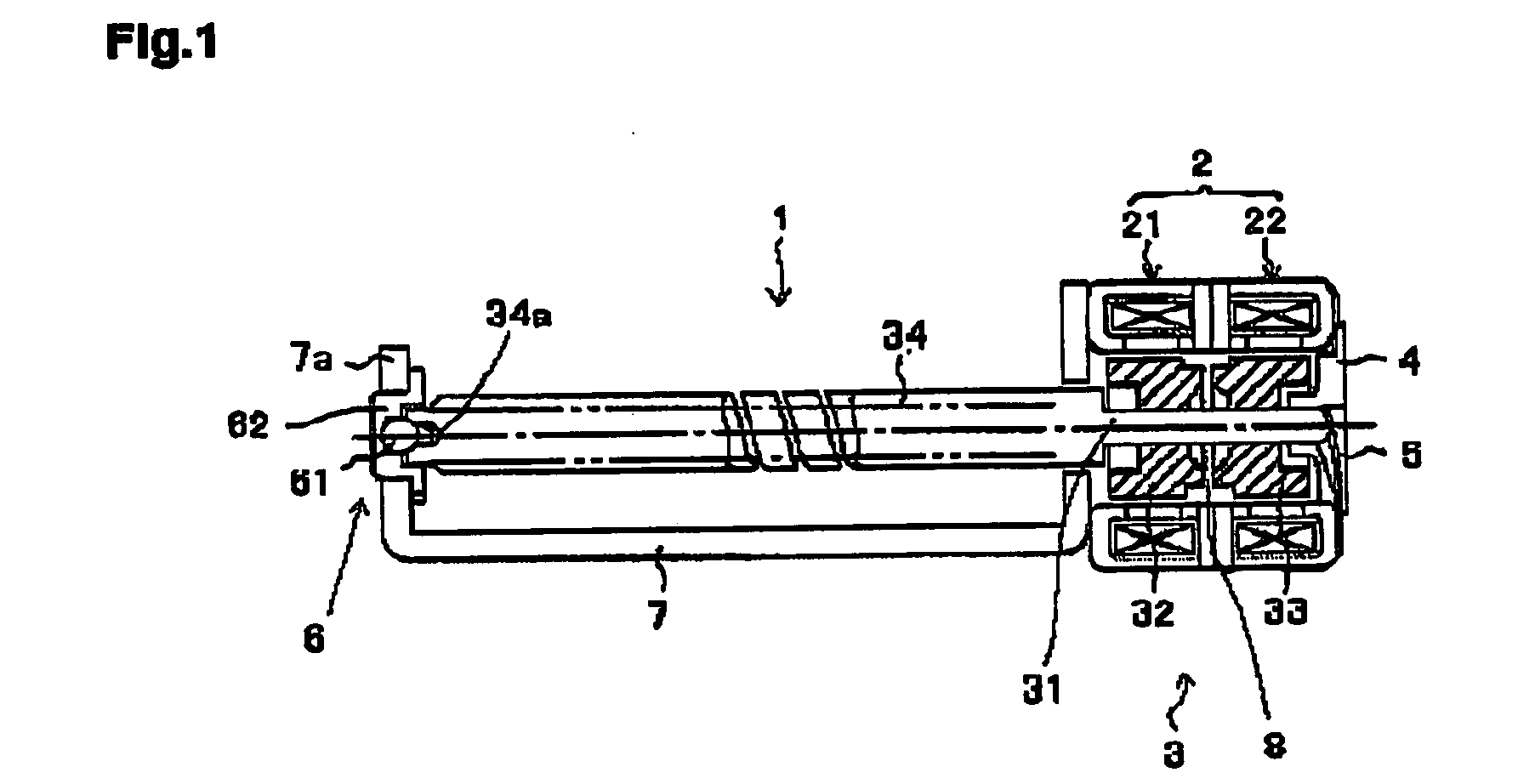
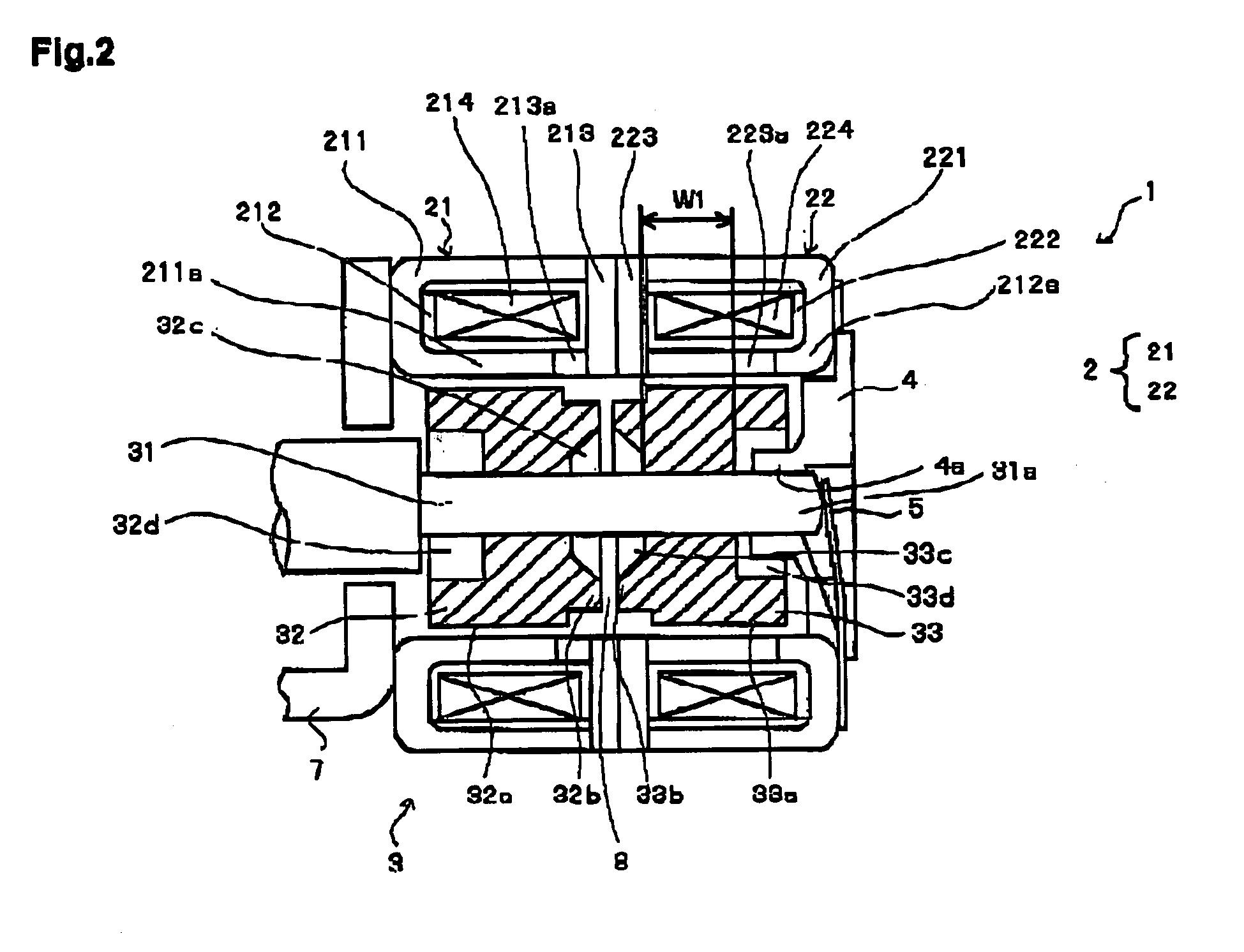
[0034]FIG. 1 is a longitudinal cross-sectional view of a motor 1 in accordance with an embodiment of the present invention. FIG. 2 is a longitudinal cross-sectional view of a main portion of the motor 1 shown in FIG. 1. FIG. 3 is a perspective view showing a cross section of a stator section and a rotor section of the motor 1 shown in FIG. 1.

[0035] The motor 1 shown in FIG. 1 is a PM (permanent magnet) type stepping motor that may be used in digital equipment such as video cameras and digital cameras.

[0036] The motor 1 is formed from a stator section 2 having a two-phase structure with first and second stator assemblies 21 and 22 and a rotor section 3. The stator section 2 includes plural comb-shaped pole teeth 211a, 213a, 221a and 223a arranged respectively along inner circumferences of the first and second stator assemblies 21 and 22 disposed in ...


PUM


Abstract

A motor includes a stator section with a two-phase structure having first and second stator assemblies disposed in an axial direction, and a plurality of pole teeth arranged at an electrical angle of 90 degrees along inner circumferences of the first and second stator assemblies, and a rotor section including a rotation shaft, and first and second permanent magnets that are disposed opposite to and spaced a predetermined gap from the pole teeth and affixed to the rotation shaft with a gap provided between the first and second permanent magnets in the axial direction. Each of the first and second permanent magnets has an effective section at an outer circumference thereof that has multiple poles alternately magnetized with N poles and S poles, and has a protruded section that has a diameter smaller than an outer diameter of the effective section and protrudes in the axial direction.

Description

BACKGROUND OF THE INVENTION [0001] 1. Field of the Invention [0002] The present invention relates to motors having a stator section equipped with first and second stator assemblies and a rotor section equipped with first and second permanent magnets respectively disposed opposite to the first and second stator assemblies. [0003] 2. Description of the Related Arts [0004] Motors having a stator section equipped with first and second stator assemblies and a rotor section equipped with first and second permanent magnets respectively disposed opposite to the first and second stator assemblies are generally called PM (permanent magnet) type stepping motors. [0005] The range of application of such PM type stepping motors has expanded as actuators for a variety of equipment because of their excellent controllability. In recent years, PM type stepping motors have been used in electronic equipment such as video cameras and digital cameras. In this connection, thinner and more miniaturized mot...

Claims


Application Information

Patent Timeline
IPC IPC(8): H02K1/12H02K5/16H02K7/08H02K1/27H02K7/116H02K37/10H02K37/14
CPCH02K37/14H02K7/1166
Inventor SHIMOYAMA, TAKESHI
Owner NIDEC SANKYO CORP
Why Eureka
Eureka Blog
Learn More