Controller of legged mobile robot

a mobile robot and control device technology, applied in the direction of electric programme control, program control, instruments, etc., can solve the problems of no effect of recovering posture, low stability and unstable posture of legged mobile robots with two legs, so as to ensure the stability of the posture of the robot.

Inactive Publication Date: 2005-05-26
HONDA MOTOR CO LTD
View PDF1 Cites 67 Cited by
  • Summary
  • Abstract
  • Description
  • Claims
  • Application Information

AI Technical Summary

Benefits of technology

[0013] According to the first aspect of this invention, the new instantaneous value of the desired movement is set based on the error between the desired state quantity of the posture of the robot and the actual state quantity of the posture of the robot so that the variable to be limited (friction force component), defined based on the dynamic model in accordance with the new instantaneous value, remains within the allowable range. Thus, it becomes possible to subsequently determine the instantaneous value of the desired movement which enables the variable to be limited, that is, the friction force component, to remain within the allowable range, and enables the error related to the state quantity of the posture of the robot (for example, the state quantity of a posture angle of the body of the robot, the center of gravity of the same and the like) to be close to zero. Therefore, by performing movement control of the robot to allow the movement of the robot to follow the instantaneous value of the desired movement, the robot can be moved with a stable posture without causing the robot to slip, even where the robot is moved on a floor surface with a small frictional force, or in a gait having a period during which a vertical component of the translation floor reaction force becomes small (for example, a running gait).
[0053] Therefore, according to the twenty-second aspects of this invention, it becomes possible to determine the group of the actual floor reaction force manipulated variable and the correction manipulated variable, which are capable of causing the error to be close to zero, improving stability of behavior of the dynamic model, and properly causing the actual floor reaction force manipulated variable and the variable to be limited to remain within the allowable range, respectively. Thus, stability of behavior of the robot can be improved.

Problems solved by technology

The stability of the legged mobile robot, particularly the legged mobile robot with two legs, is intrinsically low.
Therefore, when disturbance or the like is applied to the robot, the posture of the robot becomes unstable.
However, in this control, even when posture is disrupted, there occurs no effect of recovering the posture until the next landing.
Therefore, the posture may be largely disrupted before the next landing and the robot may fall over.
In addition, this control has the following disadvantage.
Thus, contact with the ground cannot be recovered until then.
However, when this technology is used, during a one-leg supporting period of a biped mobile robot, for example, it is sometimes infeasible to generate the total floor reaction force with the ZMP outside of the contact surface, even though the ankle joint angle is largely shifted to deliberately and greatly shift the floor reaction force of actual robot.
Hence, when the actual robot greatly inclines relative to the model, it is sometimes impossible to obtain the sufficient recovering force for bringing inclination of actual robot back to normal.
In reality, however, the errors in the inclination angles and inclination angular velocities occur as shown by a dotted line, due to a modeling error or disturbance as mentioned earlier.
In addition, the gravitational effect causes these shifts to have a tendency toward divergence in which the shifts increase more as the errors increase in magnitude.
When this technology is used, however, the range in which the actual ZMP can be shifted is limited within a foot region X sole, as shown in the drawing.
Therefore, the moment which can be generated in the direction of posture recovery is limited, and thus the posture recovery of the robot may not be pursued appropriately.

Method used


Image

  • Controller of legged mobile robot
  • Controller of legged mobile robot
  • Controller of legged mobile robot

Examples


first embodiment

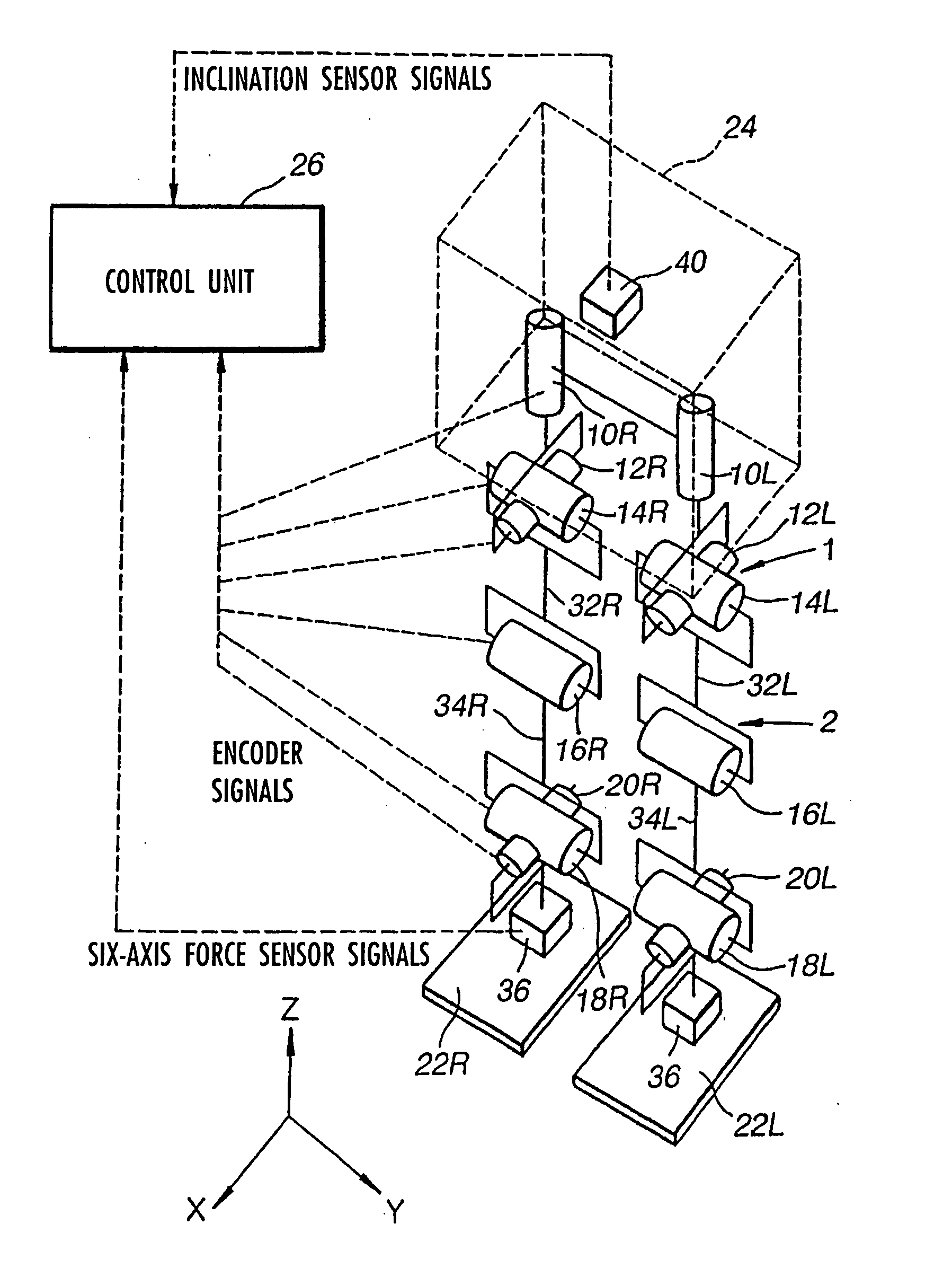
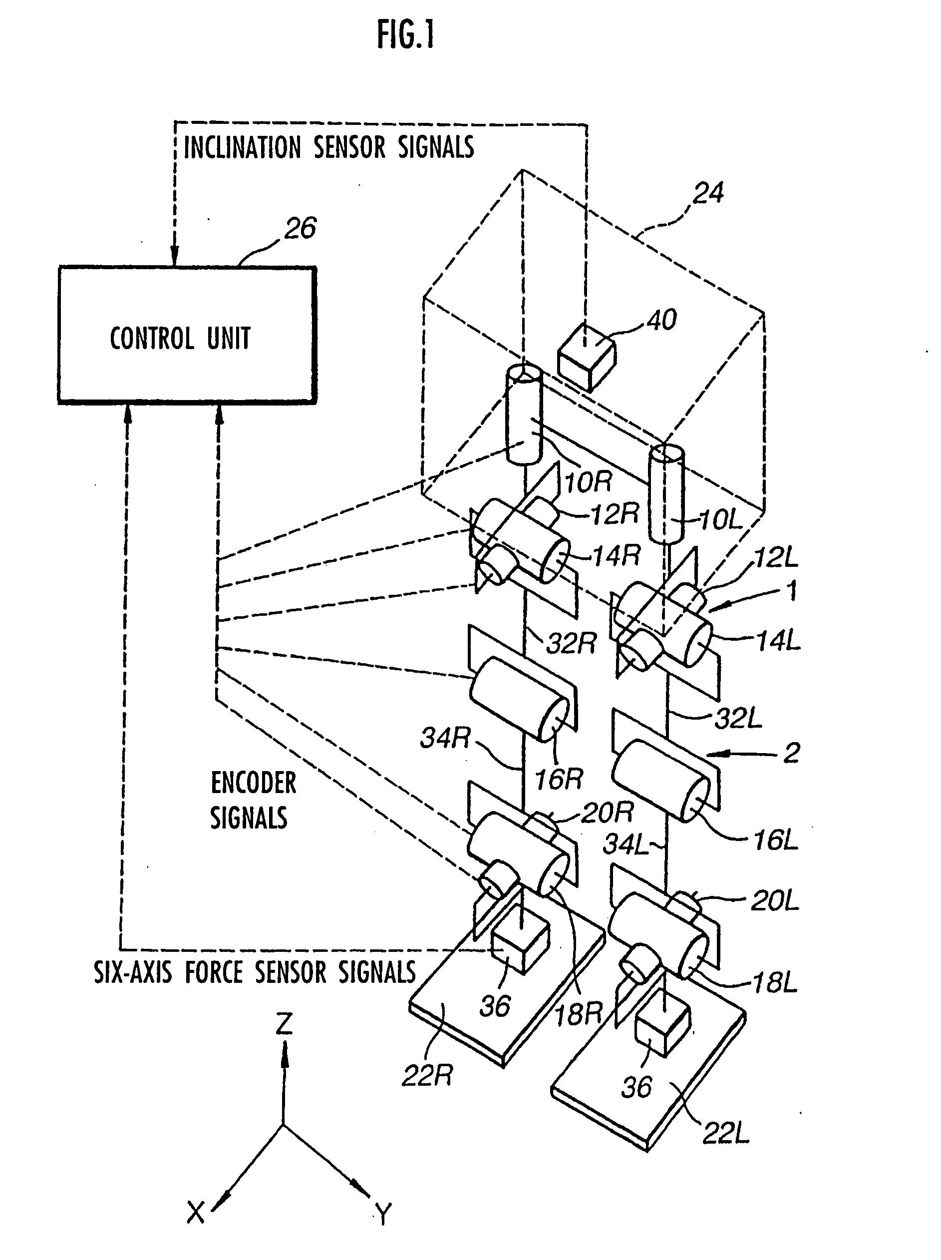
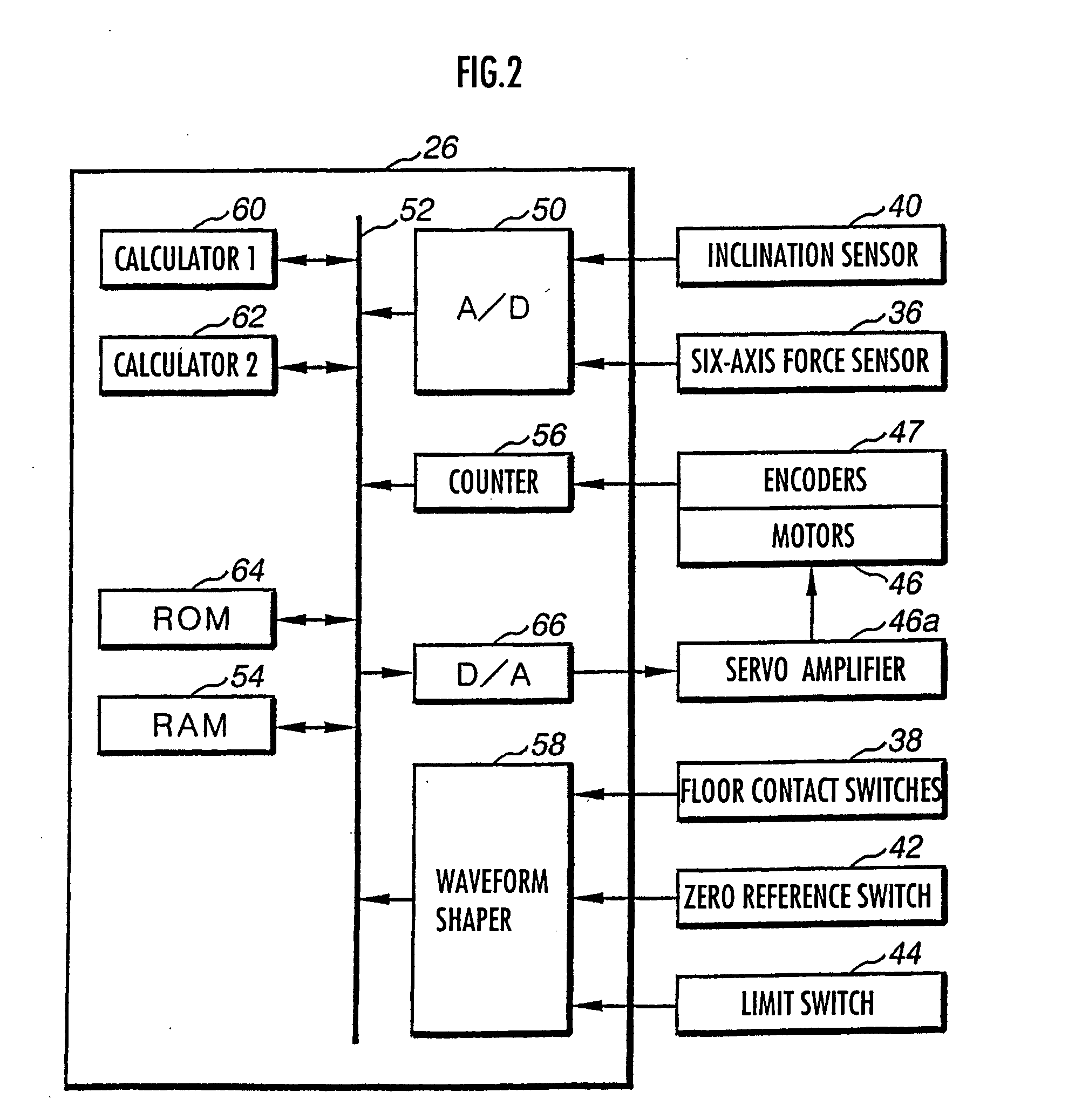
[0114]FIG. 3 is a block diagram showing the entire functional configuration of the control device of the robot 1 in this invention. Portions other than the “actual robot” in FIG. 3 are configured by processing functions (mainly functions of the first calculator 60 and the second calculator 62) executed by the control unit 26. In the description below, Reference Symbols R and L are omitted when it is not necessary to identify the right and left legs 2.

[0115] The actuation of the control device of this embodiment is outlined with reference to FIG. 3. The control unit 26 generates a desired gait by the use of a gait generating device 100 as described later. The desired gait generated and outputted by the gait generating device 100 includes desired body position / posture trajectories (trajectories of desired position and posture of the body 24), desired foot position / posture trajectories (trajectories of desired position and posture of each foot 22), desired arm posture trajectories (tra...

second embodiment

[0429] The floor reaction force's moment allowable range is for limiting the desired floor reaction force's moment of the compliance control, in order to prevent such problems. To be precise, the floor reaction force's moment allowable range is set for a recovery condition 1 described in the second embodiment described later. However, in the case of satisfying forgoing Equation d27 like this embodiment, setting the floor reaction force's moment allowable range for the recovery condition 1 is equivalent to limiting the desired floor reaction force's moment for compliance control not to exceed the floor reaction force's moment allowable range.

[0430] Therefore, it is preferred that the floor reaction force's moment allowable range be set so that the floor reaction force central point allowable range obtained by dividing the floor reaction force's moment allowable range by the floor reaction force's vertical component, is included in the range where the ZMP can exist.

[0431] To be more ...

third embodiment

[0500] As shown in each of FIGS. 53 and 54, where are intersection points between the line having the aforementioned inclination h and the aforementioned allowable range region (rectangular regions in each drawing), (Fltd, Mltd) are determined as values of the floor reaction force's horizontal component and floor reaction force's moment which correspond to an intersection point (black circle in the drawings) closest to the point of (Fin, Min) among the above-mentioned intersection points. When the group of (Fltd, Mltd) is determined in this manner, it is prioritized that the model's body posture angle stabilization floor reaction force's moment obtained by the use of later-described Equations e01 and e02 coincides with the required value of model's body posture angle stabilization floor reaction force's moment Mrfdmd. Based on this, the model's body horizontal position stabilization floor reaction force's moment becomes closest to the required value of model's body horizontal positi...


PUM


Abstract

A control device for a legged mobile robot, in which a correction manipulated variable of a desired floor reaction force (desired floor reaction force's moment) is subsequently determined based on an error between an actual state quantity, such as a body posture angle, of the robot 1 and a desired state quantity of the same, and at the same time, a desired movement of the robot 1 is subsequently determined by the use of the correction manipulated variable and a dynamic model. At this time, a friction force component, which defines a frictional force between the robot 1 and a floor such as a translation floor reaction force's horizontal component, is set as a variable to be limited, and an allowable range of the variable to be limited is set. The desired movement is determined so that the variable to be limited remains within the allowable range and a resultant force of an inertial force and gravity, generated by the movement of the robot 1 on the dynamic model, balances with a floor reaction force obtained by correcting the desired floor reaction force by the correction manipulated variable. The desired movement is determined by adjusting a plurality of movement modes having mutually different generation ratios of a floor reaction force's moment and a translation floor reaction force.

Description

TECHNICAL FIELD [0001] The present invention relates to a control device for a legged mobile robot and more specifically to a control device for a legged mobile robot, provided with an internal model generating a desired gait of the robot, causing behavior of the robot (actual robot) to follow behavior of the internal model. BACKGROUND ART [0002] Known as a legged mobile robot, particularly as a legged mobile robot with two legs, is a robot described in, for example, Japanese Patent Laid-Open Publication No. Showa 62-97005 and Japanese Patent Laid-Open Publication No. Showa 63-150176. Control of robots including the legged mobile robot is detailed in, for example, Robotics Handbook, Robotic Society of Japan, Oct. 20, 1990. [0003] The stability of the legged mobile robot, particularly the legged mobile robot with two legs, is intrinsically low. Therefore, when disturbance or the like is applied to the robot, the posture of the robot becomes unstable. Thus, it is preferred that an inc...

Claims


Application Information

Patent Timeline
Patent Type & Authority Applications(United States)
IPC IPC(8): B62D57/02B62D57/032
CPCB62D57/032B62D57/02B25J5/02
Inventor TAKENAKA, TORUMATSUMOTO, TAKASHIYOSHIIKE, TAKAHIDE
Owner HONDA MOTOR CO LTD
Why Eureka
Try Eureka