
Clock recovery circuit and communication device

Inactive Publication Date: 2005-05-26
ADVANTEST CORP
View PDF3 Cites 59 Cited by
  • Summary
  • Abstract
  • Description
  • Claims
  • Application Information

AI Technical Summary

Benefits of technology

[0007] Therefore, it is an object of the present invention to provide a clock recovery circuit and a communication device, which is capable of overcoming the above drawbacks accompanying the conventional art. The above and other objects can be achieved by combinations described in the independent claims. The dependent claims define further advantageous and exemplary combinations of the present invention.

Problems solved by technology

However, in the fine delay circuit used together with the voltage controlled oscillator (VCO) of the DLL circuit, a variable amount as much as compensating the change of the processes, the noise, and the change of the environmental conditions is needed, so the circuit size increases and besides the degree of the eye opening of the data due to the phase noise of the PLL circuit becomes narrow.

Method used


Image

  • Clock recovery circuit and communication device
  • Clock recovery circuit and communication device
  • Clock recovery circuit and communication device

Examples


Embodiment Construction

[0038] The invention will now be described based on the preferred embodiments, which do not intend to limit the scope of the present invention, but exemplify the invention. All of the features and the combinations thereof described in the embodiment are not necessarily essential to the invention.

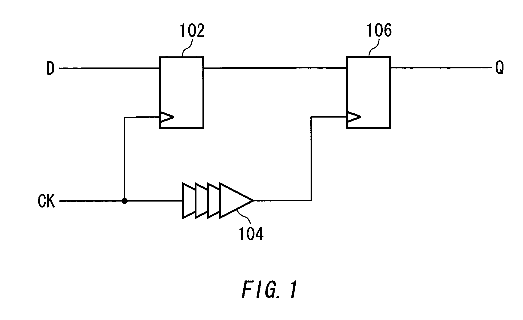
[0039]FIG. 1 shows an example of the configuration of a timing comparator 100 according to this invention. The timing comparator 100 includes a dynamic D flip-flop circuit 102, a buffer 104 and a positive feedback D flip-flop circuit 106, and samples and outputs a data signal (D) by a clock signal (CK). The dynamic D flip-flop circuit 102 latches and outputs the data signal (D) by its parasitic capacitance based on the clock signal (CK) received by the timing comparator 100 and supplies it to the positive feed back D flip-flop circuit 106. The buffer 104 delays the clock signal (CK) received by the timing comparator 100 by a predetermined time and supplies it to the positive feedback D flip...


PUM


Abstract

A clock recovery circuit includes plural stages of first variable delay elements for sequentially delaying a data signal by a first delay amount, plural stages of second variable delay elements for sequentially delaying a clock signal by a second delay amount which is larger than the first delay amount, a plurality of timing comparators for sampling a plurality of the data signals delayed by the plural stages of first variable delay elements with the clock signal delayed by the second variable delay elements of the same stages, a plurality of EOR circuits for performing exclusive OR operation on a pair of sampling results by a pair of the sequential timing comparators, and a recovery variable delay circuit for delaying the clock signal based on the operation result of the plurality of EOR circuits.

Description

[0001] This patent application claims priority from a Japanese patent application No.2003-391456filed on Nov. 20, 2003, the contents of which are incorporated herein by reference. BACKGROUND OF THE INVENTION [0002] 1. Field of the Invention [0003] The present invention relates to a clock recovery circuit and a communication device. More particularly, the present invention relates to a clock recovery circuit for adjusting the timing of a clock signal against a data signal and a communication device provided with the clock recovery circuit. [0004] 2. Description of the Related Art [0005] A communication LSI employs a clock recovery circuit for adjusting the phase of a clock signal to retrieve a data signal. Such clock recovery circuit compares the phases of the data signal and the clock signal and adjusts the phase of the clock signal using a variable delay circuit. A conventional variable delay circuit is configured with a rough delay circuit whose resolution is low and variable amou...

Claims


Application Information

Patent Timeline
IPC IPC(8): G01R31/319H03K5/00H03K5/01H03L7/081H04L1/20H04L1/24H04L7/00H04L7/02
CPCG01R31/31922H03K5/135H03K2005/00026H03L7/0805H04L7/0037H04L1/205H04L1/24H04L7/0008H04L7/0041H03L7/0812H03L7/0816H03K5/01H04L7/02
Inventor SUDA, MASAKATSUSUDOU, SATOSHIOKAYASU, TOSHIYUKI
Owner ADVANTEST CORP
Features
  • Generate Ideas
  • Intellectual Property
  • Life Sciences
  • Materials
  • Tech Scout
  • Unparalleled Data Quality
  • Higher Quality Content
  • 60% Fewer Hallucinations
Learn More