Power efficiency control output buffer
- Summary
- Abstract
- Description
- Claims
- Application Information
AI Technical Summary
Benefits of technology
Problems solved by technology
Method used
Image

Examples
Embodiment Construction
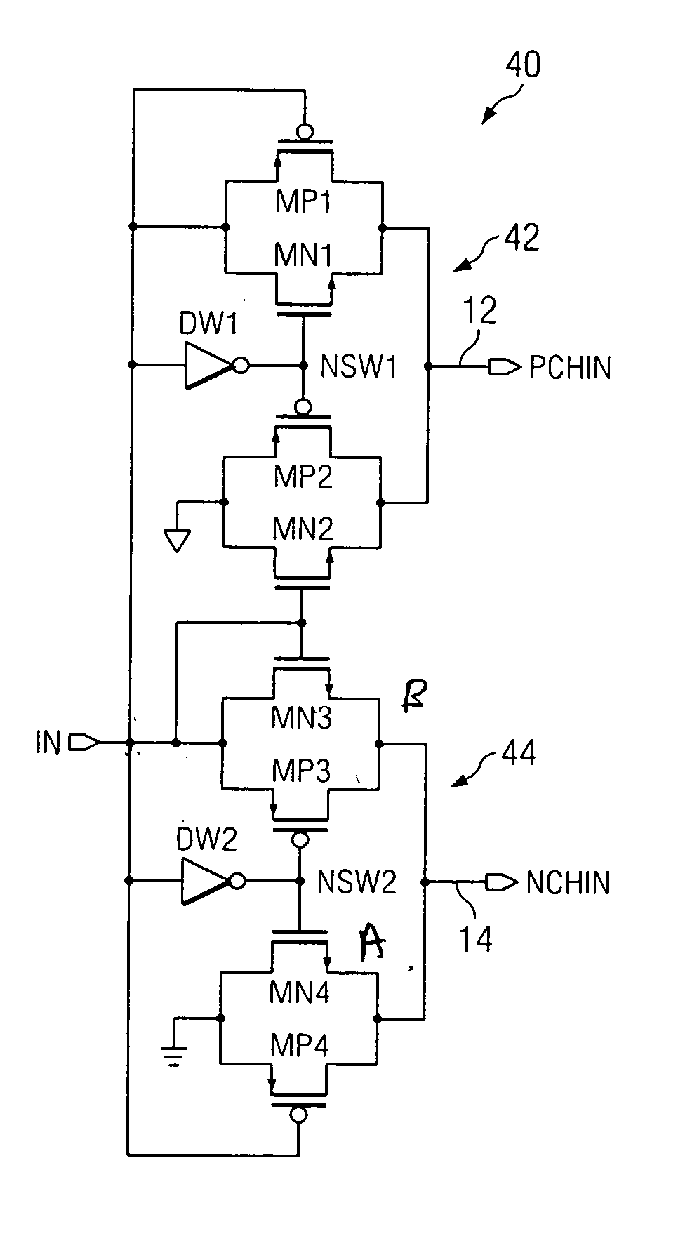
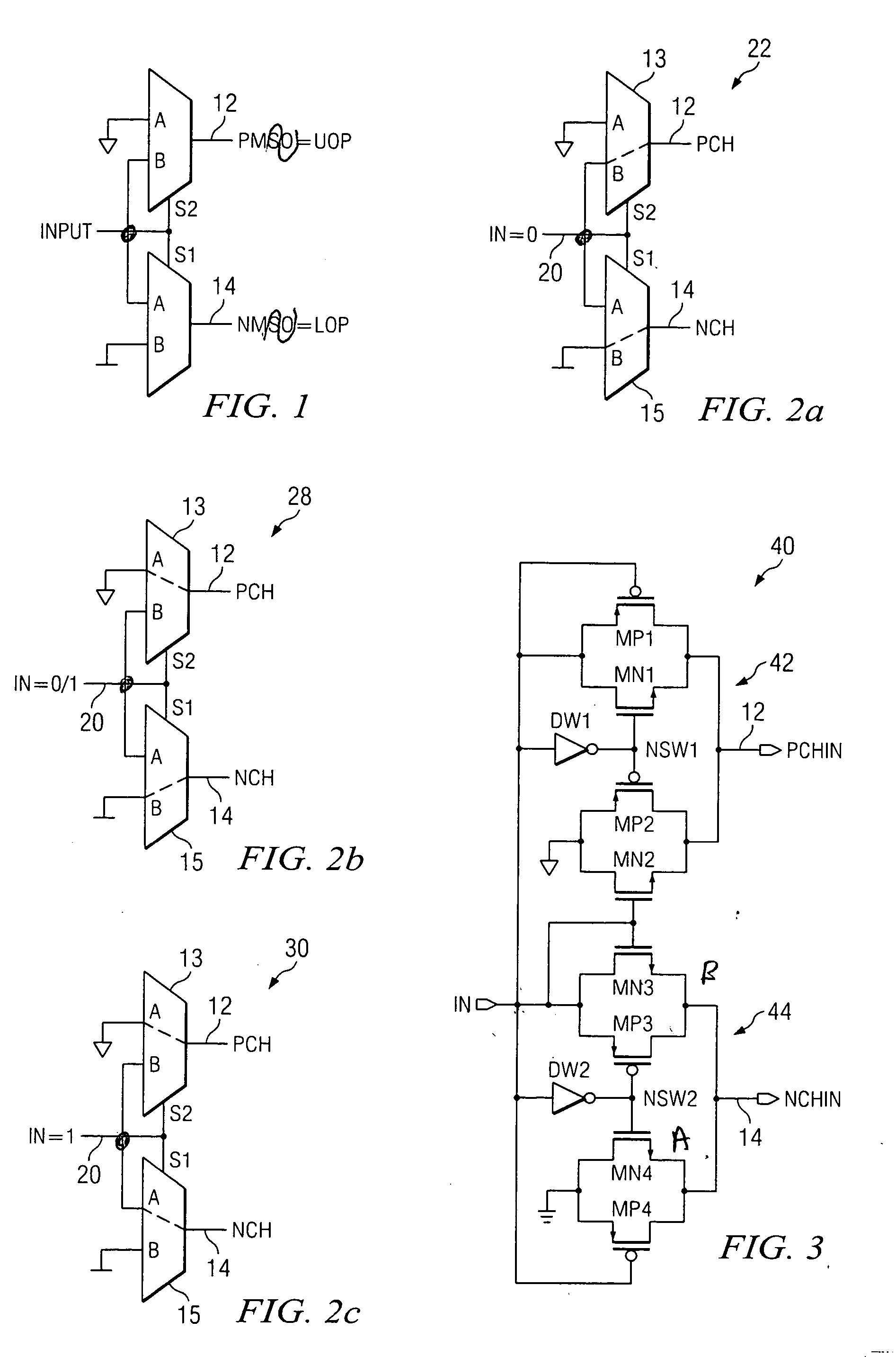
[0022]FIG. 1 depicts the logic operation associated with the UOP (upper output) driver 12 and LOP (lower output) driver 14 for a power efficiency control (PEC) circuit 10. The present inventor alone recognized the key to eliminating short circuit power consumption is to momentarily tri-state the output before every transition. This concept implies the pull-up and pull-down transistors must be driven by independent sources (input Pch=1 while input Nch=0). The power efficiency control circuit 10 to meet this purpose is described in further detail herein below
[0023]FIGS. 2a, b, c illustrate the low-to-high transition of an input signal versus switch connections for the PEC circuit 10 depicted in FIG. 1. Operation of the PEC circuit 10 is defined in three stages with reference to FIGS. 2a, b, c. Consider now a low-to-high transition on the input 20. FIG. 2a shows the first stage 22 in which input 20 is low. The multiplexers 13, 15 are configured such that Nch 14 is connected to Gnd, wh...
PUM
 Abstract
Description
Claims
Application Information