Microstrip antenna

a microstrip antenna and antenna body technology, applied in the direction of flexible antennas, flexible aerials, protective materials radiating elements, etc., can solve the problems of difficult to attach the conventional microstrip antenna to a garment, a cap or the like, and achieve the effect of easy sewn, light weight, and easy sewn

Inactive Publication Date: 2005-05-26
NAT INST OF INFORMATION & COMM TECH
View PDF7 Cites 24 Cited by
  • Summary
  • Abstract
  • Description
  • Claims
  • Application Information

AI Technical Summary

Benefits of technology

[0007] A microstrip antenna of the present invention comprises a flexible dielectric substrate, a flexible ground plate being conductive and provided on a lower surface of said dielectric substrate, and a microstrip patch being provided on the upper surface of said dielectric substrate, smaller in area than said ground plate, flexible and conductive. According to the microstrip antenna of the present invention, a wearable antenna can be obtained which is light in weight, flexible, substantially crease-free, capable of being mounted in a non-flat place, and capable of being attached to (e.g., being sewn on) a wearing article such as a garment or a cap.
[0008]

Problems solved by technology

Therefore, it is difficult to attach the conventiona

Method used


Image

  • Microstrip antenna
  • Microstrip antenna
  • Microstrip antenna

Examples


Embodiment Construction

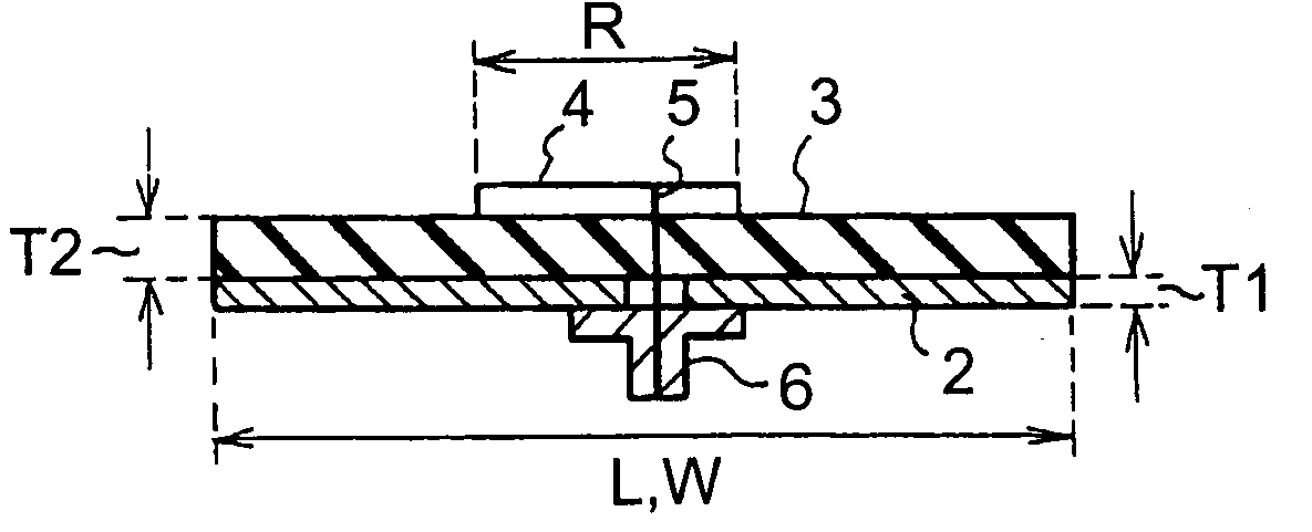
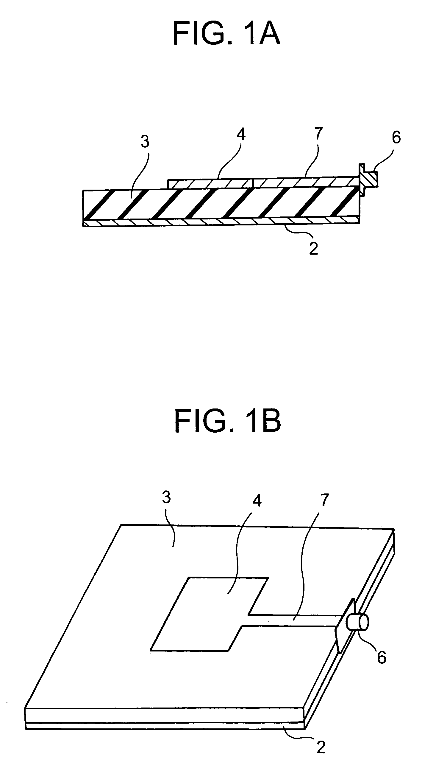
[0019]FIGS. 1A and 1B are diagrams showing a microstrip antenna of the present invention. Referring to FIG. 1, the microstrip antenna has a ground plate 2, a dielectric substrate 3, a microstrip patch 4, a connector 6 and a feed conductor (microstrip line) 7.

[0020] The microstrip antenna of the present invention has such elements as described below for solving the above-described problem.

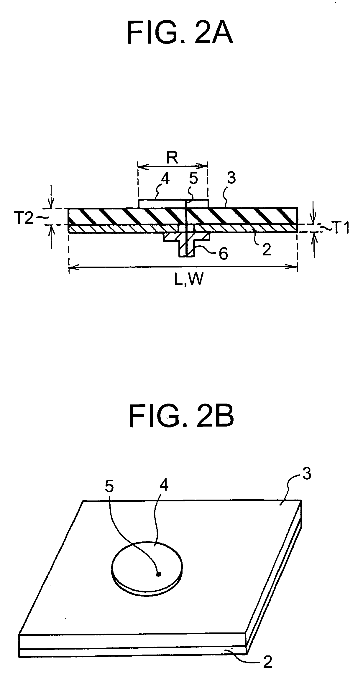
[0021] That is, the microstrip antenna of the present invention includes the flexible dielectric substrate 3, the flexible ground plate 2 which is conductive and is provided on the lower surface of the dielectric substrate 3, and the flexible microstrip patch 4 which is conductive, is provided on the upper surface of the dielectric substrate 3 and has an area smaller than that of the ground plate 2. Further, the feed conductor 7 is also flexible and conductive. Therefore, according to the microstrip antenna of the present invention, a wearable antenna can be obtained which is light in weight, flex...


PUM


Abstract

A microstrip antenna has a flexible dielectric substrate (3), a flexible conductive ground plate (2) provided on a lower surface of the dielectric substrate (3), and a flexible conductive microstrip patch (4) provided on the upper surface of the dielectric substrate (3), smaller in area than the ground plate (2).

Description

TECHNICAL FIELD [0001] This invention relates to a microstrip antenna, and more particularly to a microstrip antenna which is light in weight, flexible, substantially crease-free and can be attached to a wearing article such as a garment and a cap, or which will be a wearable antenna. BACKGROUND ART [0002] A microstrip antenna is used as an antenna for a mobile station such as a motor vehicle, an antenna for a cellular phone, an antenna for satellite communication, and an antenna for receiving a satellite broadcast, etc. [0003]FIG. 9 is a diagram showing an example of a conventional microstrip antenna. The conventional microstrip antenna shown in FIG. 9 has a feed circuit substrate 11, a ground plate (ground conductor) 12, an antenna substrate (dielectric) 13, a microstrip patch 14, a feed pin 15, and a feed conductor 16. [0004] The ground plate 12 is a conductor provided between the antenna substrate 13 and the feed circuit substrate 11. The feed conductor 16 is provided on the fee...

Claims


Application Information

Patent Timeline
IPC IPC(8): H01Q13/08H01Q1/08H01Q1/27H01Q1/38H01Q1/40H01Q9/04
CPCH01Q1/085H01Q1/27H01Q1/40H01Q1/38H01Q1/273H01Q13/08
Inventor TANAKA, MASATOJANG, JAE-HYEUK
Owner NAT INST OF INFORMATION & COMM TECH
Why Eureka
Try Eureka