Driving a plasma display panel (PDP)

a plasma display and display panel technology, applied in the direction of identification means, instruments, static indicating devices, etc., can solve the problems of large current instantaneously flowing, noise and electromagnetic interference (emi) in the driving circuit, and instability of the driving circuit, so as to reduce emi and noise

Inactive Publication Date: 2005-05-26
SAMSUNG SDI CO LTD
View PDF13 Cites 15 Cited by
  • Summary
  • Abstract
  • Description
  • Claims
  • Application Information

AI Technical Summary

Benefits of technology

[0014] Therefore, it is an aspect of the present invention to provide an apparatus to drive a plasma display panel, which is capable of reducing EMI and noise by changing a current path when a driving operation moves from an address period to a sustain period.

Problems solved by technology

In order to drop all of the Y electrode voltages to 0V at the same time, low-voltage driving switches of all scan ICs are turned on at the same time, thereby causing a very large amount of current to instantaneously flow in the scan ICs, resulting in noise and ElectroMagnetic Interference (EMI) in a driving circuit as well as instability of the driving circuit.

Method used


Image

  • Driving a plasma display panel (PDP)
  • Driving a plasma display panel (PDP)
  • Driving a plasma display panel (PDP)

Examples


first embodiment

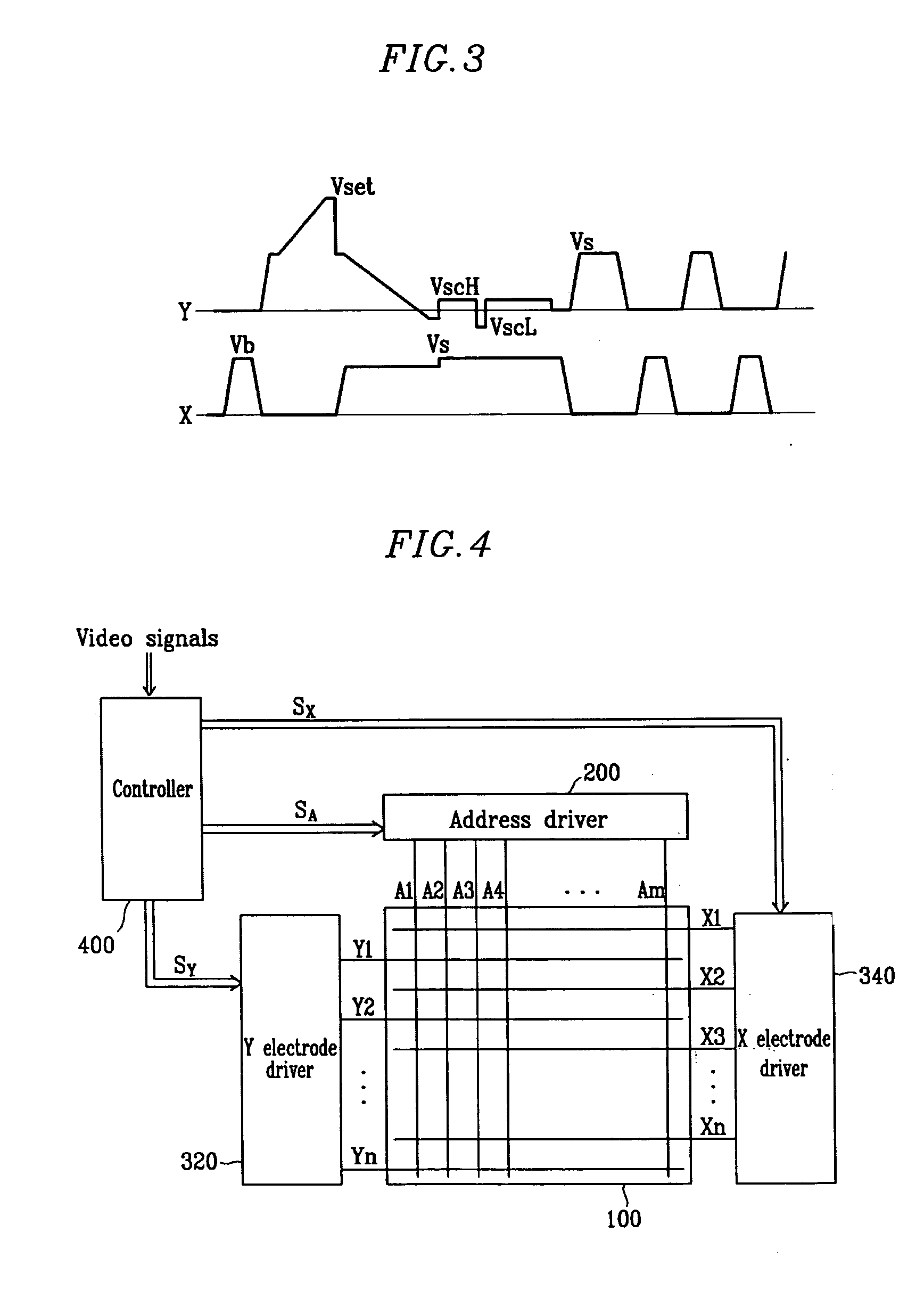
[0057]FIG. 5 is a detailed circuit diagram of the X and Y electrode drivers 340 and 320 of the PDP according to the present invention.

[0058] As shown in FIG. 5, a circuit for driving the PDP according to the first embodiment of the present invention includes the X electrode driver 340 and the Y electrode driver 320. The Y electrode driver 320 includes a reset driver 321, a scan driver 322 and a sustain driver 323.

[0059] The reset driver 321 includes a rising ramp generator for generating a rising reset waveform during a reset period. The rising ramp generator includes a voltage source Vset-Vs for supplying a voltage Vset-Vs, a capacitor Cset operated with a floating voltage, a ramp switch Yrr, and a switch Ypp for preventing a reverse flow of current. The switch Ypp is arranged on a main path along which a sustain discharge voltage generated by the sustain driver 323 is supplied to a panel capacitor Cp. The reset driver 321 further includes a falling ramp generator for generating a...

second embodiment

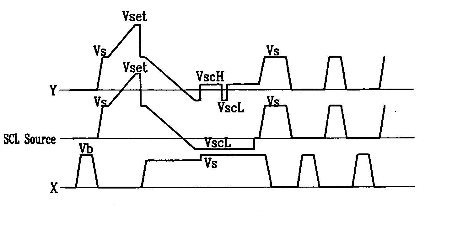
[0083] A method of driving the PDP according to the present invention will hereinafter be described in detail with reference to FIGS. 8 and 9.

[0084]FIG. 8 is a waveform diagram of driving waveforms of the PDP according to the second embodiment of the present invention, and FIG. 9 is a circuit diagram illustrating a current path when the driving waveforms according to the second embodiment of the present invention are supplied.

[0085] As shown in FIG. 8, in the second embodiment of the present invention, when a driving operation moves from the address period to the sustain period, the Y electrode voltage is floated to the voltage VscH and then reduced to 0V through the power recovery circuit of the X electrode driver and, thereafter, a sustain discharge voltage is supplied to the Y electrode.

[0086] That is, at the time that a scan operation is completed, the switch SCH is turned on and the switch SCL is turned off. In this state, the switch SCH is turned off to float the output of t...


PUM


Abstract

In driving a Plasma Display Panel (PDP), when a driving operation moves from an address period to a sustain period, low-voltage driving switches of all of the scan ICs are turned on at the same time after the drain voltage and source voltage of each of them are made equal via a power recovery circuit under the condition that the outputs of the scan ICs are floating. Therefore, when the switches are turned on, no current flows therethrough, thereby making it possible to solve instability of a driving circuit and noise and EMI therein.

Description

CLAIM OF PRIORITY [0001] This application makes reference to, incorporates the same herein, and claims all benefits accruing under 35 U.S.C. §119 from an application for APPARATUS AND METHOD FOR DRIVING PLASMA DISPLAY PANEL earlier filed in the Korean Intellectual Property Office on 24 Nov. 2003 and there duly assigned Serial No. 10-2003-0083603. BACKGROUND OF THE INVENTION [0002] 1. Field of the Invention [0003] The present invention relates to driving a Plasma Display Panel (PDP). [0004] 2. Description of the Related Art [0005] Recently, PDPs are being highlighted as flat panel displays in that they are superior to other flat panel displays with regard to high luminance, high luminous efficiency and a wide viewing angle. [0006] A PDP uses a plasma generated by a gas discharge to display characters or images. The PDP includes, according to its size, more than several tens to millions of pixels arranged in the form of a matrix. [0007] The PDP includes two glass substrates spaced apa...

Claims


Application Information

Patent Timeline
Patent Type & Authority Applications(United States)
IPC IPC(8): G09G3/20G09F9/313G09G3/10G09G3/288G09G3/291G09G3/293G09G3/294G09G3/296G09G3/298H01J17/49
CPCG09G3/293G09G3/294G09G2330/06G09G3/2965G09G3/296
Inventor LEE, JOO-YUL
Owner SAMSUNG SDI CO LTD
Why Eureka
Try Eureka