Method and apparatus for measuring chromatic dispersion

a technology of chromatic dispersion and chromatic dispersion ring, which is applied in the direction of instruments, optical apparatus testing, structural/machine measurement, etc., can solve the problems of difficult automation of the measurement of the difficult to obtain an accurate amount of chromatic dispersion, and complicated configuration of optical transmitter and optical receiver

Inactive Publication Date: 2005-05-26
KDDI CORP
View PDF3 Cites 21 Cited by
  • Summary
  • Abstract
  • Description
  • Claims
  • Application Information

AI Technical Summary

Benefits of technology

[0028] According to exemplary embodiments of the invention, since main parts are configurated with optical elements, it is possible to measure chromatic dispersion without using a high-speed electric circuit. In addition, chromatic dispersion can be measured in a wide range and also a polarity of chromatic dispersion can be judged.

Problems solved by technology

However, measured results of the above-stated first and second conventional methods are affected by factors except the amount of chromatic dispersion, such as polarization mode dispersion (PMD) and an optical signal to noise ratio (OSNR) and therefore it is difficult to obtain an accurate amount of chromatic dispersion.
Furthermore, in a configuration in which a PMD compensator is added, it is difficult to automatize the measurement of the amount of chromatic dispersion.
In the second conventional method, since it is necessary to dispose additional apparatuses on both transmitter and receiver sides, there is a disadvantage that the configurations of an optical transmitter and an optical receiver become complicated.
Although the third conventional method has an advantage of low dependency on PMD and OSNR, it is necessary to dispose two high-speed optoelectric converters, two clock extractors, and a phase comparator to compare a phase of outputs from the two clock extractors and accordingly the configuration becomes expensive and large-sized.

Method used


Image

  • Method and apparatus for measuring chromatic dispersion
  • Method and apparatus for measuring chromatic dispersion
  • Method and apparatus for measuring chromatic dispersion

Examples


Embodiment Construction

[0037] Explanatory embodiments of the invention are explained below in detail with reference to the drawings.

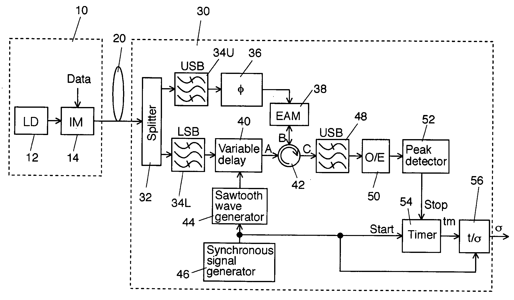
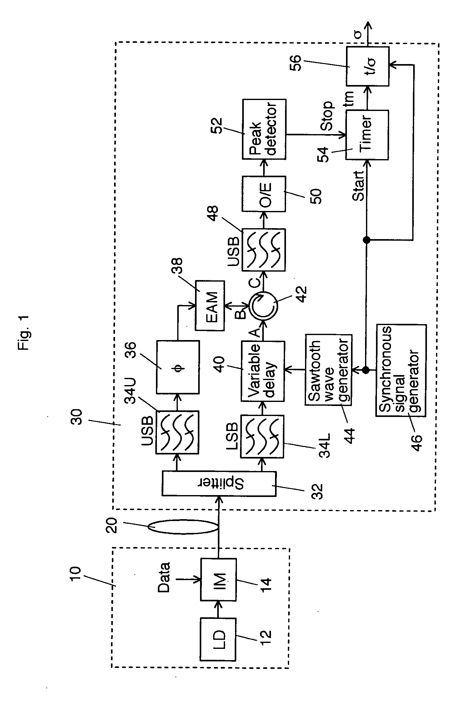
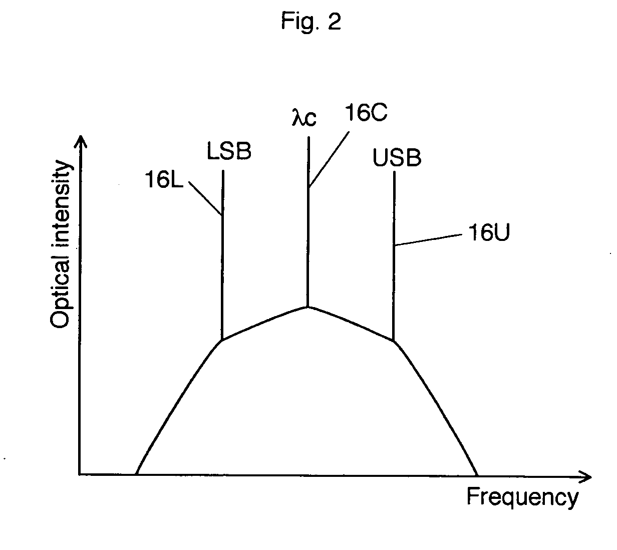
[0038]FIG. 1 shows a schematic block diagram of a first explanatory embodiment according to the invention. A test signal light generator 10 includes a laser light source 12 of a wavelength λc and an intensity modulator 14 to intensity-modulate an optical output from the laser light source 12 with a data. The intensity-modulated signal light from the intensity modulator 14 is input to an optical transmission line 20 as a test signal light. FIG. 2 shows a spectral example of the intensity-modulated signal light to be input to the optical transmission line 20. The horizontal axis expresses frequency and the vertical axis expresses optical intensity. A peak 16C in the center shows an optical carrier of the wavelength λc, a peak 16U on the high frequency side shows an upper side band (USB), and a peak 16L on the low frequency side shows a lower sideband (LSB).

[0039] In this firs...


PUM

PropertyMeasurementUnit
chromatic dispersionaaaaaaaaaa
timeaaaaaaaaaa
phaseaaaaaaaaaa

Abstract

A test signal light intensity-modulated with a test data is generated and enters the optical transmission line. An extractor extracts the first and second optical components from the test signal light output from the optical transmission line, the first and second optical components composed of any one of a main signal light component, an upper sideband component, and/or a lower sideband component. A time difference measuring apparatus measures a time difference between the first and second optical components. A converter converts the measured time difference into a chromatic dispersion value.

Description

CROSS REFERENCE TO RELATED APPLICATIONS [0001] This application claims priority to Japanese Patent Application No. 2003-394996, filed Nov. 26, 2003, the entire contents of which are incorporated herein by reference. FIELD OF THE INVENTION [0002] This invention relates to method and apparatus for measuring chromatic dispersion. BACKGROUND OF THE INVENTION [0003] In an optical fiber transmission system, an influence of chromatic dispersion in an optical fiber transmission line is inevitable. Accordingly, means to measure an amount of chromatic dispersion in an optical transmission line are demanded. Well-known means are disclosed in the following three references: (1) A. Sano et al., “Automatic dispersion equalization by monitoring extracted-clock power level in a 40-Gbit / s, 200-km transmission line,” Tu3.5, Vol. 2, pp. 207-209, ECOC'96; (2) M. N. Peterson et al., “Dispersion monitoring and compensation using single in-band Subcarrier tone,” WH4, OFC2001; and (3) Q. Yuetal., “Chromati...

Claims


Application Information

Patent Timeline
Patent Type & Authority Applications(United States)
IPC IPC(8): G01M11/02G01M11/00H04B10/07H04B10/073H04B10/079H04B10/54
CPCG01M11/338G01M11/333
Inventor HAYASHI, MICHIAKITANAKA, HIDEAKI
Owner KDDI CORP
Why Eureka
Try Eureka