
Shielded-ergonomic microscope stages

Inactive Publication Date: 2005-05-26
LEICA MICROSYSTEMS CMS GMBH
View PDF2 Cites 5 Cited by
  • Summary
  • Abstract
  • Description
  • Claims
  • Application Information

AI Technical Summary

Benefits of technology

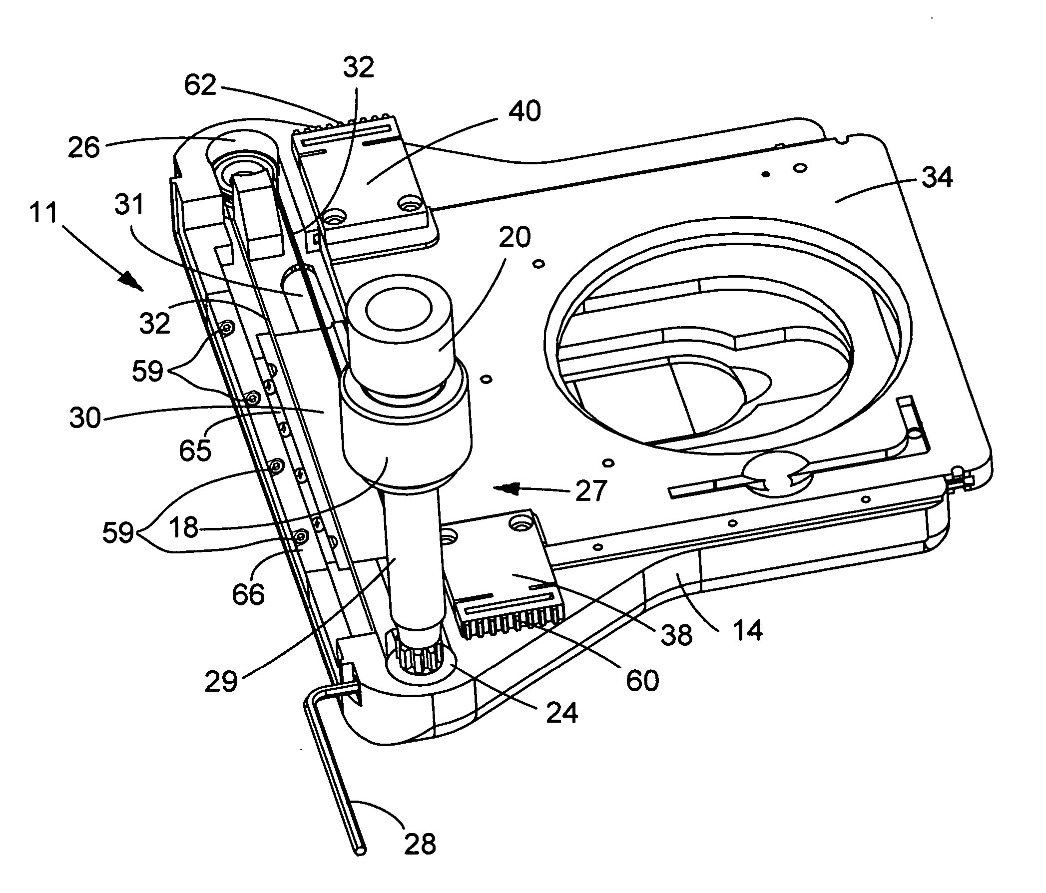
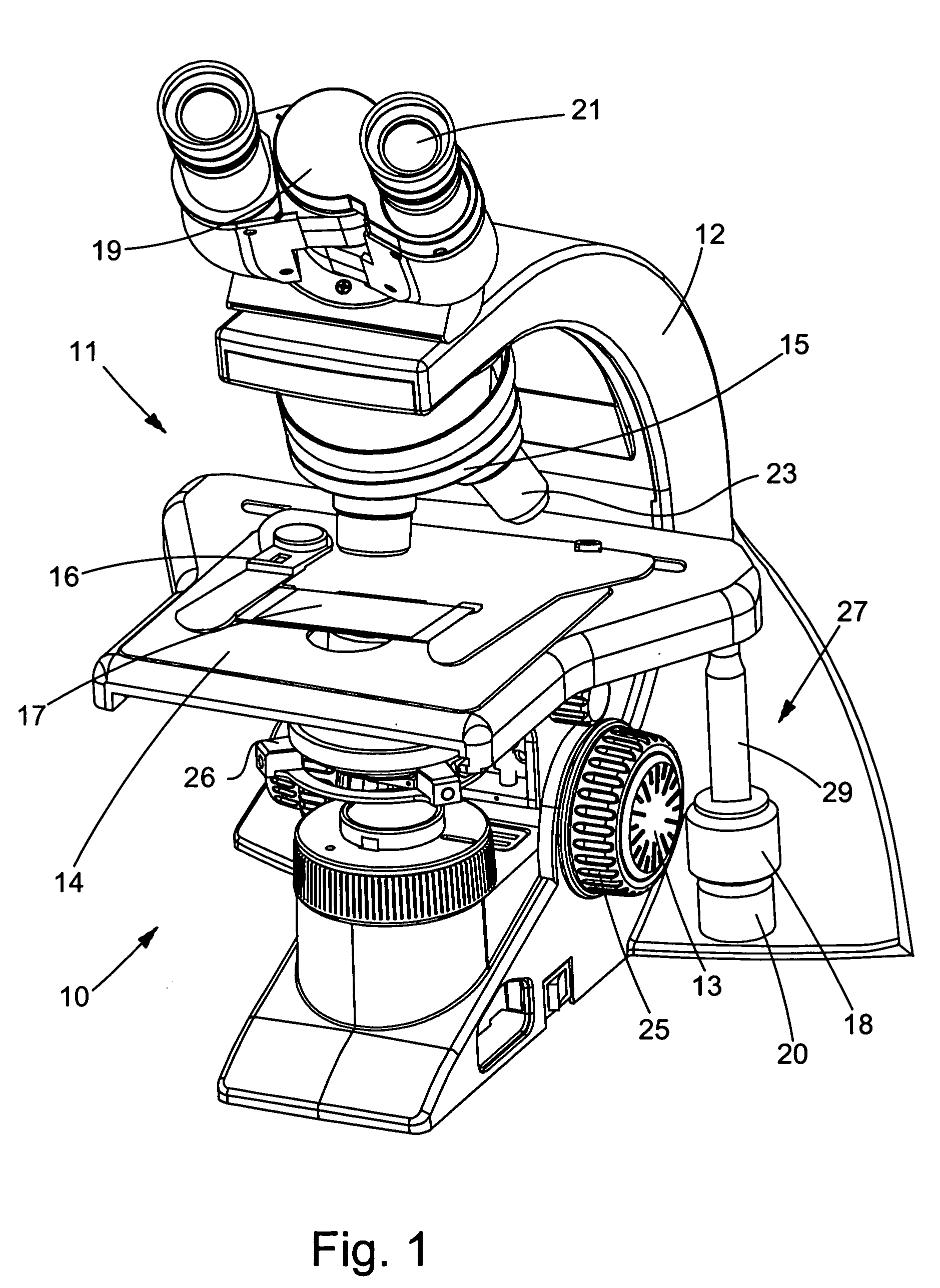
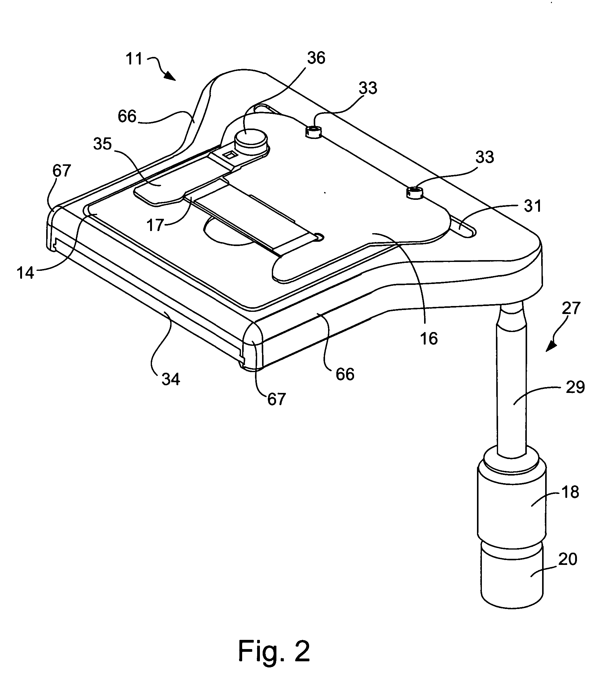
[0010] It is therefore one principal object of the invention to provide for a microscope stage assembly wherein all or practically all components are positioned on the bottom side of the stage so they are more effectively shielded from dust and debris accumulating in key parts of the assembly, while simultaneously allowing full movement of the specimen and stage in x, y and / or z axes. This is accomplished principally by means of a slot in the stage enabling the specimen retainer to be connected to the drive assembly directly through the floor of the microscope stage where it engages with a drive system. Preferably, the specimen retainer is also of sufficient width to overlap and cover substantially the entire width of the slot in the stage floor further shielding components of the drive system from dust and debris.
[0016] It is still a further object of the invention to provide the foregoing microscope stage assembly featuring a stage configuration wherein the peripheral edge(s) of the stage comprises a rim, and more particularly, a rim that is rounded, including corners of the stage that are sufficiently rounded to avoid pressure points. The rounded rim, according to this aspect of the invention, renders a microscope so equipped more ergonomic, especially for the user who employs the “hand-drive” technique, by the elimination of sharp contact points on at least one edge, i.e., one or more edges of a microscope stage.

Problems solved by technology

Typically, movement of the carriage will result in lateral movement of the specimen retaining means, and concomitantly the specimen slide, adjusting the position of the specimen within the optical path along the x-axis, i.e., so the specimen slide moves laterally, to the right or to the left relative to the floor of the stage.

Method used


Image

  • Shielded-ergonomic microscope stages
  • Shielded-ergonomic microscope stages
  • Shielded-ergonomic microscope stages

Examples


Embodiment Construction

[0032] It should be appreciated at the outset that while the present invention relates to an “Shielded-Ergonomic Microscope Stages”, the Assignees of the present application for patent have developed certain other improvements to microscopes described in United States patent applications entitled “Interchangeable Microscope Stage Drive Assembly”, “Releasable / Interchangeable Fine Focus Knob for a Microscope”, “Ergonomically Arranged Object Adjustment Controls”, “Lamp Assembly for a Microscope” and “Means for Transporting a Microscope”, which applications are filed concurrently herewith by the Assignees of the present application for patent, which applications are incorporated herewith by reference in their entireties.

[0033] Additionally, it should be appreciated that like drawing numbers on different drawing views identify identical structural elements of the invention. While the present invention is described with respect to what is presently considered to be the preferred embodime...


PUM


Abstract

Advanced microscope stages are shielded from dust and debris collecting on components by placing all or virtually all stage components below the stage floor. The shielded stages comprise a stage having a top side and a bottom side, an opening in the stage floor in the form of a linear slot, a carriage positioned adjacent to the slot for movement in a direction generally parallel with the slot, drive means for the carriage and stage, specimen retaining means on the top side of the stage, and means for affixing the specimen retaining means to the carriage through the opening in the stage floor. The advanced microscope stages may also have more ergonomic structural features with rounded rims and corners for greater user comfort.

Description

CROSS REFERENCE TO RELATED APPLICATIONS [0001] This application for patent is a Continuation-in-Part of U.S. patent application Ser. No. 10 / 721,695, filed Nov. 25, 2003 and Ser. No. 10 / 733,628 filed Dec. 11, 2003.FIELD OF THE INVENTION [0002] The present invention relates generally to microscopy, and more specifically, to microscope stages adapted for improved ergonomics and shielding from dust and debris. BACKGROUND OF THE INVENTION [0003] As is well known, a microscope is an optical instrument used to view, examine and study very small objects. There are many different types of microscopes, each best suited to particular applications. These include compound microscopes, stereomicroscopes, confocal microscopes, inverted microscopes, and laser microscopes, to name but a few. [0004] The present invention relates generally to compound microscopes and to those microscopes that are equipped with sample stages capable of being controlled by stage drive mechanisms. [0005] Microscopes have...

Claims


Application Information

Patent Timeline
IPC IPC(8): G02B21/24G02B21/26
CPCG02B21/26G02B21/242
Inventor BONAVENTURA, RUSSELLPARKS, SCOTTGILBERT, MANFRED
Owner LEICA MICROSYSTEMS CMS GMBH
Learn More