

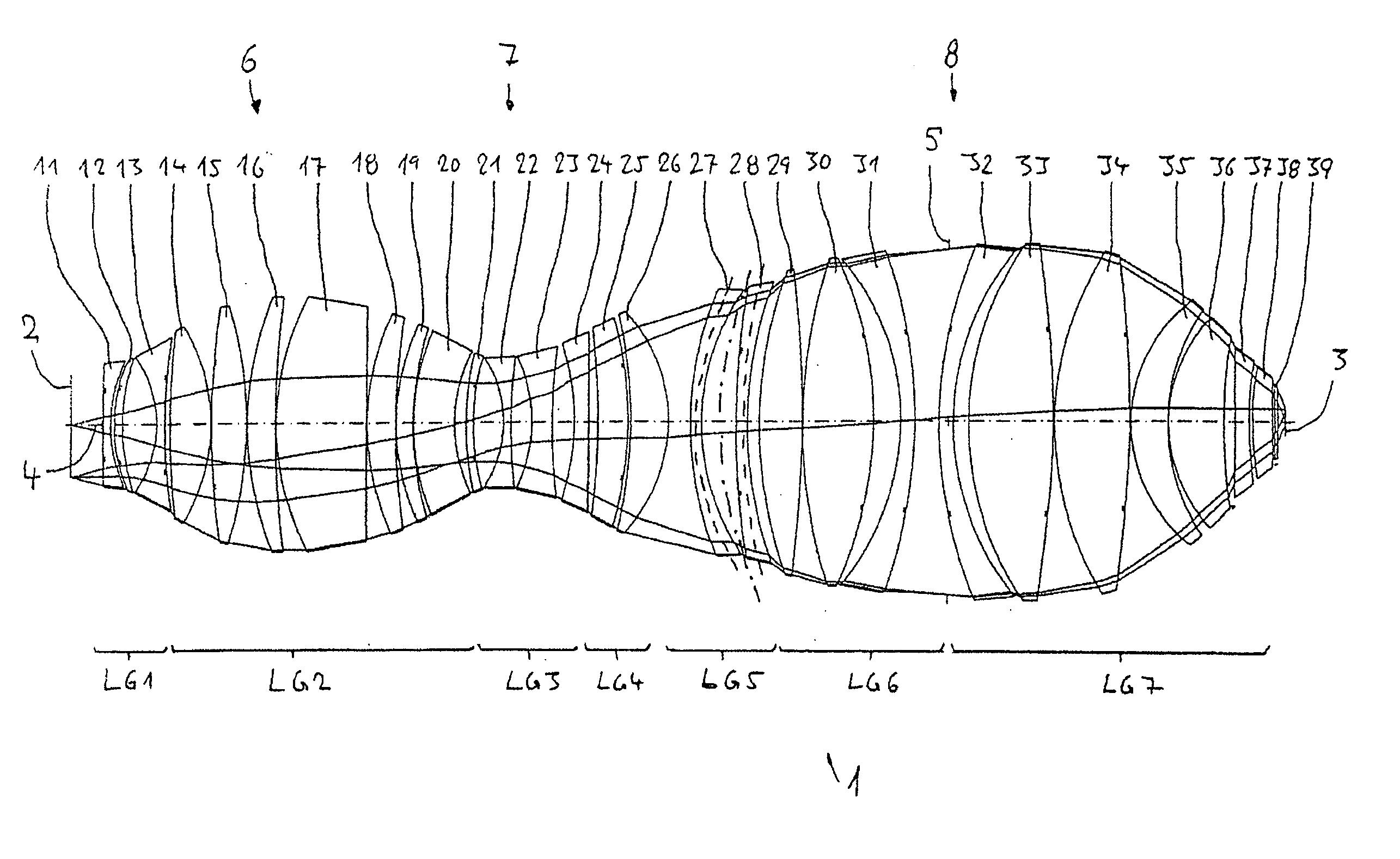
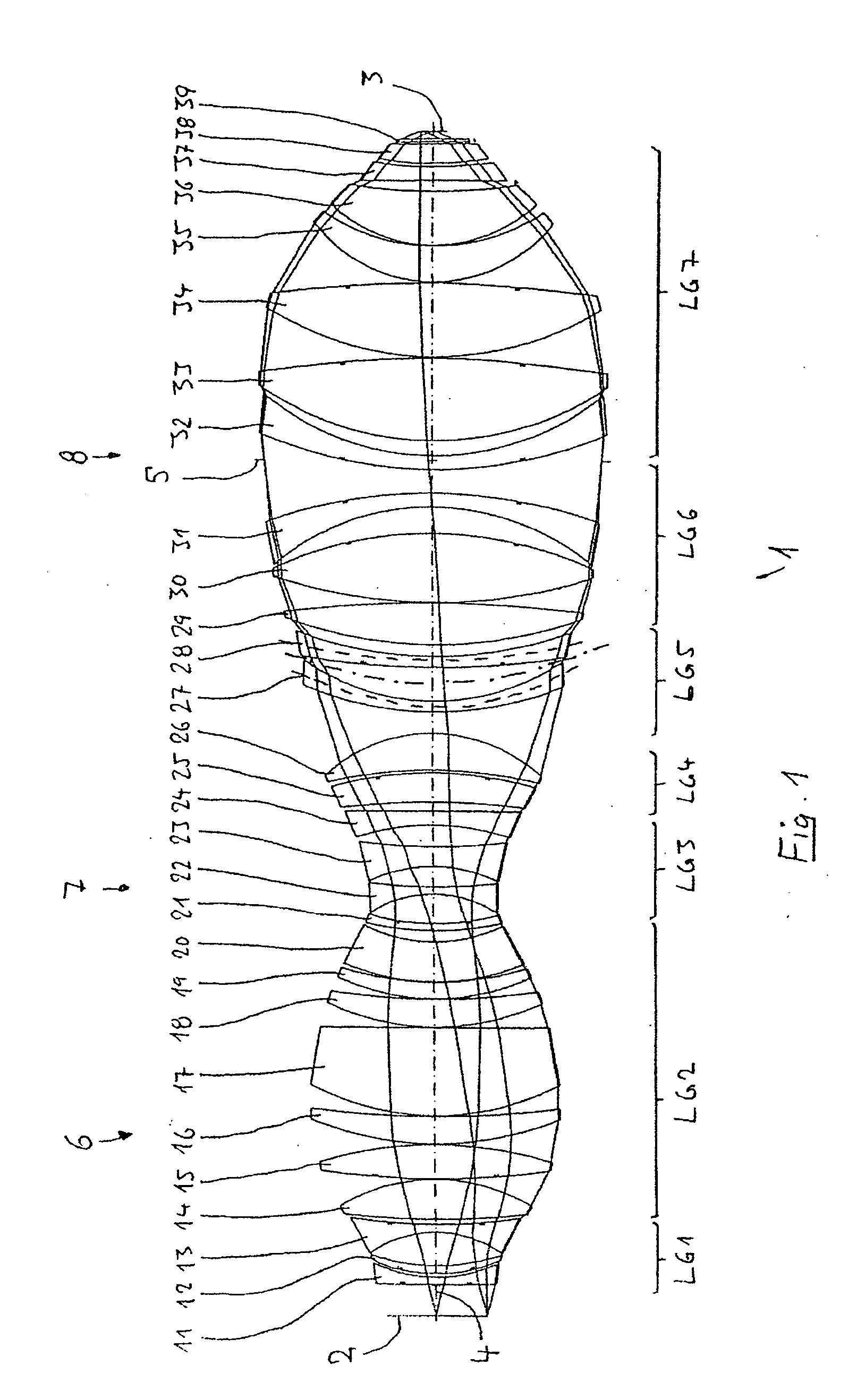
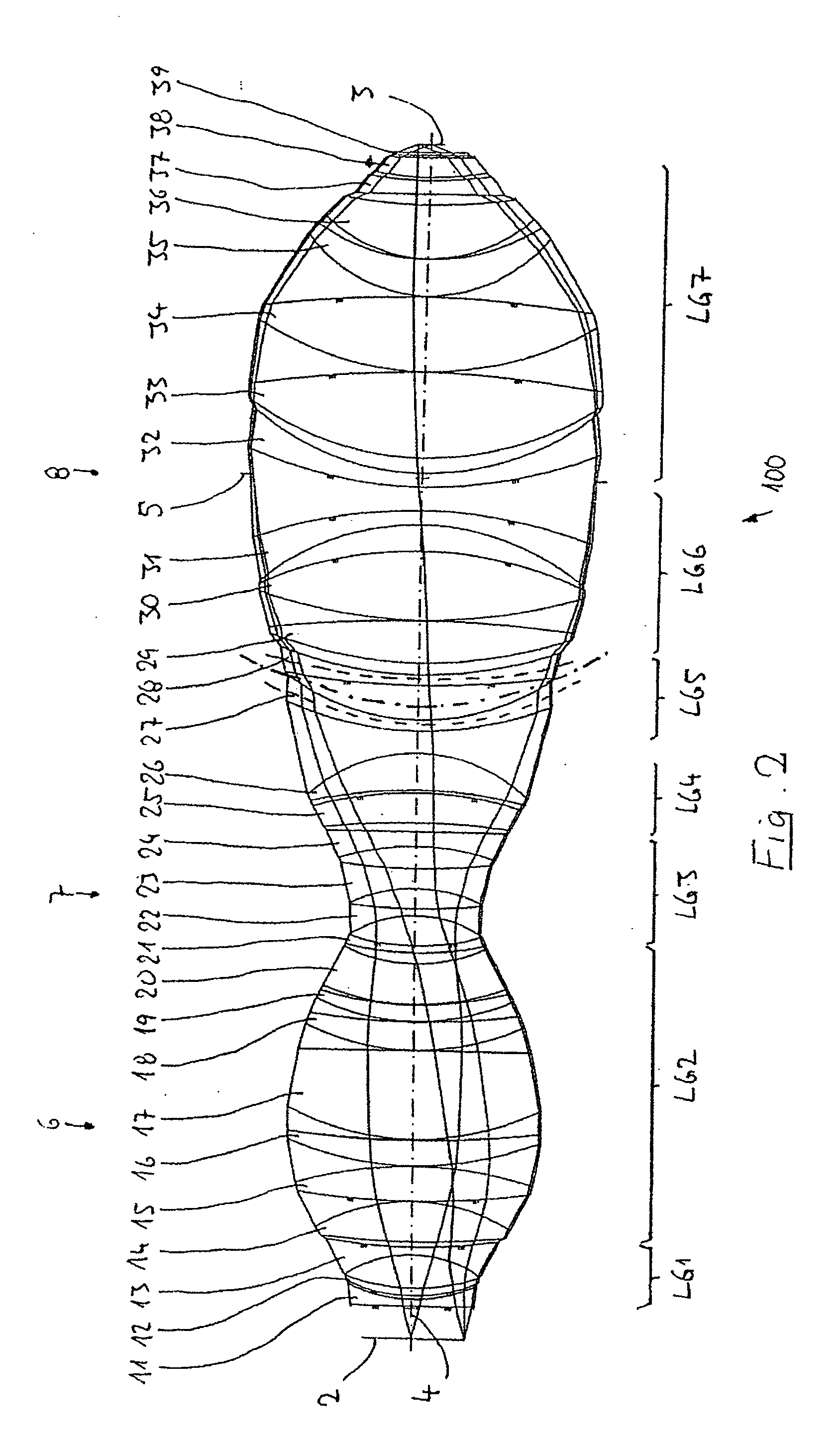
Very-high aperture projection objective
a projection objective and very high aperture technology, applied in the field of projection objectives, can solve the problems of increasing the cost of such projection objectives, difficult to provide very high aperture systems with adequate small chromatic aberrations, and increasing the volume of optical lens materials, so as to improve chromatic correction, save material, and high image-side numerical aperture
- Summary
- Abstract
- Description
- Claims
- Application Information
AI Technical Summary
Benefits of technology
Problems solved by technology
Method used
Image

Examples
Embodiment Construction
[0047] In the following description of the preferred embodiment, the term “optical axis” denotes a straight line through the centers of curvature of the spherical optical components or through the axes of symmetry of aspheric elements. Directions and distances are described as on the image side, on the wafer side or towards the image when they are directed in the direction of the image plane or the substrate which is located there and is to be exposed, and as on the object side, on the reticle side or towards the object when they are directed towards the object with reference to the optical axis. In the examples, the object is a mask (reticle) with the pattern of an integrated-circuit, but another pattern, for example a grating, can also be involved. In the examples, the image is formed on a wafer serving as substrate and provided with a photoresist layer, but other substrates are also possible, for example elements for liquid crystal displays or substrates for optical gratings.
[00...
PUM
| Property | Measurement | Unit |
|---|---|---|
| operating wavelength | aaaaa | aaaaa |
| operating wavelength | aaaaa | aaaaa |
| operating wavelength | aaaaa | aaaaa |
Abstract
Description
Claims
Application Information