Catadioptric projection objective

a catadioptric and objective technology, applied in the field of catadioptric projection objective, can solve the problems of insufficient color correction, limited material selection, and insufficient transparency of purely refractive system, and achieve the effect of high image side numerical apertur

Inactive Publication Date: 2009-07-30
CARL ZEISS SMT GMBH
View PDF100 Cites 2 Cited by
  • Summary
  • Abstract
  • Description
  • Claims
  • Application Information

AI Technical Summary

Benefits of technology

[0022]It is one object of the invention to provide a catadioptric projection objective suitable for use in the vacuum ultraviolet (VUV) range having potential for very high image side numerical aperture which may be extended to values allowing immersion lithography at numerical apertures NA>1. It is another object to provide catadioptric projection objectives that can be build with relatively small amounts of optical material. It is yet another object to provide compact high-aperture catadioptric projection objectives having moderate size.
[0034]In these embodiments a circular pupil centered around the optical axis is be provided in a centered optical system. Two or more concave mirrors in the system parts contributing to forming the second intermediate image are provided, where the used area of the concave mirrors deviates significantly from an axial symmetric illumination. In preferred embodiments exactly two concave mirrors are provided and are sufficient for obtaining excellent imaging quality and very high numerical aperture. Systems having one common unfolded (straight) optical axis can be provided which facilitate manufacturing, adjustment and integration into photolithographic exposure systems. No planar folding mirrors are necessary. However, one or more planar folding mirrors could be utilized to obtain more compact designs.
[0045]It is known that aspheric surfaces provided on optical elements, such as lenses, mirrors and / or essentially planar faces of plates, prisms or the like can be utilized to improve both the correction status and the overall size and material consumption of optical systems. In some embodiments, the projection objective includes at least one “double asphere” comprising a first aspheric surface and a second aspheric surface immediately adjacent to the first aspheric surface, thereby allowing a transmitted beam to pass two subsequent aspheric surfaces without passing an intermediate spheric or planar surface. Double aspheres have proven to be a very powerful correction means in some embodiments.
[0049]As pointed out earlier, avoiding large numbers of aspheric surfaces on lenses may contribute to facilitating manufacturing of the projection objective. Under certain conditions, the correcting action of a single aspheric surface can be approximated by one or more spherical surfaces where large angles of incidence of rays occur on that surface. In some embodiments, the first objective part includes at least one lens having a lens surface where incidence angles of rays transiting that lens surface include incidence angles larger than 60°. Preferably, that surface may be optically close to the pupil surface The angle of incidence (incidence angle) in this case is defined as the angle enclosed by a ray and the surface normal of the lens surface at the point of impingement of that ray on the lens surface. High incidence angle surfaces of that kind may be employed to reduce the number of aspheres.

Problems solved by technology

However, there are very few materials, in particular, synthetic quartz glass and crystalline fluorides, that are sufficiently transparent in that wavelength region available for fabricating the optical elements required.
Since the Abbé numbers of those materials that are available lie rather close to one another, it is difficult to provide purely refractive systems that are sufficiently well color-corrected (corrected for chromatic aberrations).
Further, the high prices of the materials involved and limited availability of crystalline calcium fluoride in sizes large enough for fabricating large lenses represent problems.
However, since the reflecting surfaces of the concave mirrors are interrupted at the bores, the pupil of the system is obscured.
The authors conclude that physically realizable systems of this type have poor image quality.

Method used


Image

  • Catadioptric projection objective
  • Catadioptric projection objective
  • Catadioptric projection objective

Examples


first embodiment

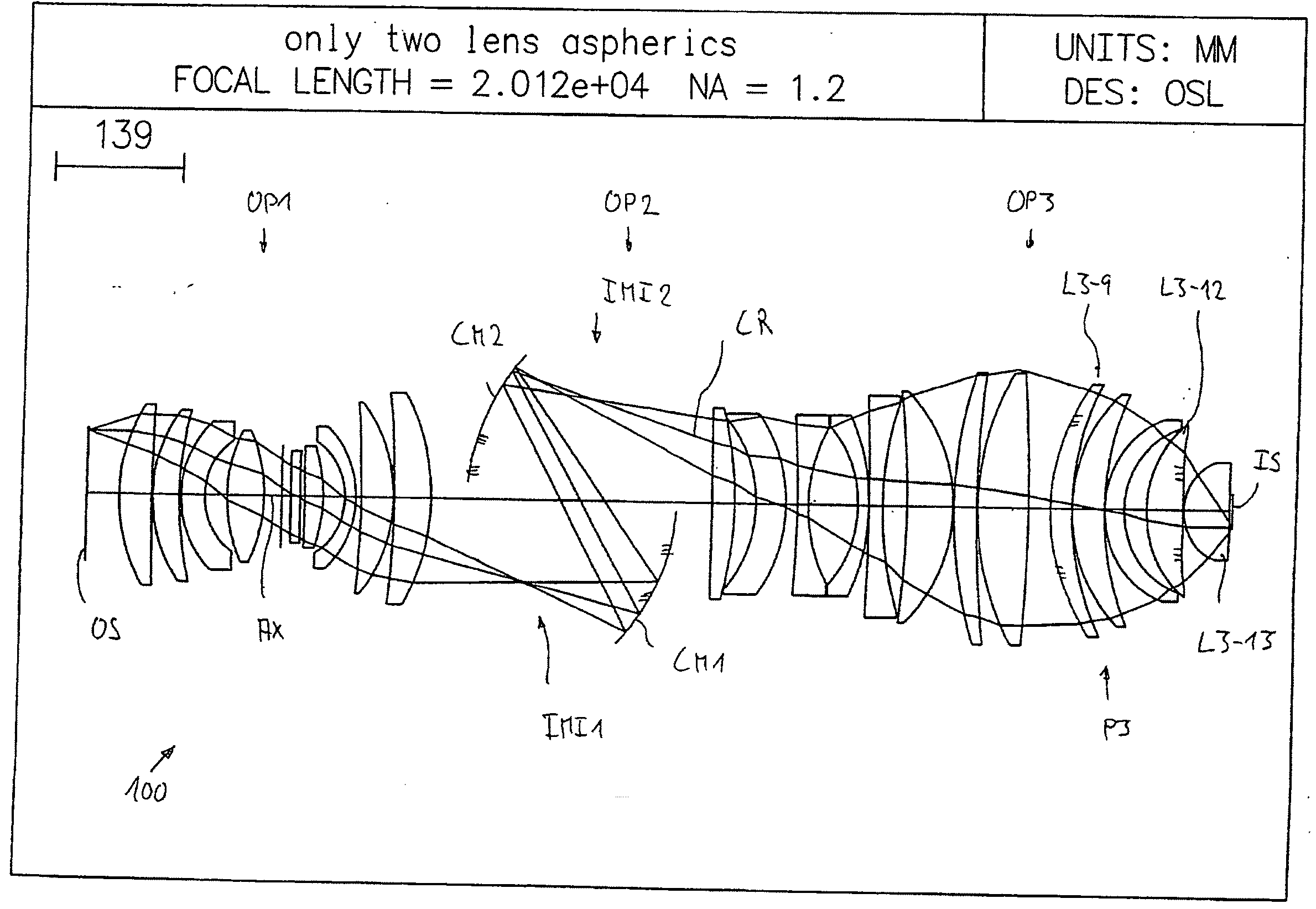
[0069]FIG. 1 shows a catadioptric projection lens 100 according to the invention designed for ca 193 nm UV working wavelength. It is designed to project an image of a pattern on a reticle arranged in the planar object surface OS (object plane) into the planar image surface IS (image plane) on a reduced scale, for example, 4:1, while creating exactly two real intermediate images IMI1, IM12. A first refractive objective part OP1 is designed for imaging the pattern in the object surface into the first intermediate image IMI1 at an enlarged scale. A second, catoptric (purely reflective) objective part OP2 images the first intermediate image IMI1 into the second intermediate image IM12 at a magnification close to 1:1. A third, refractive objective part OP3 images the second intermediate image IM12 onto the image surface IS with a strong reduction ratio. The second objective part OP2 comprises a first concave mirror CM1 having the concave mirror surface facing the object side, and a secon...

second embodiment

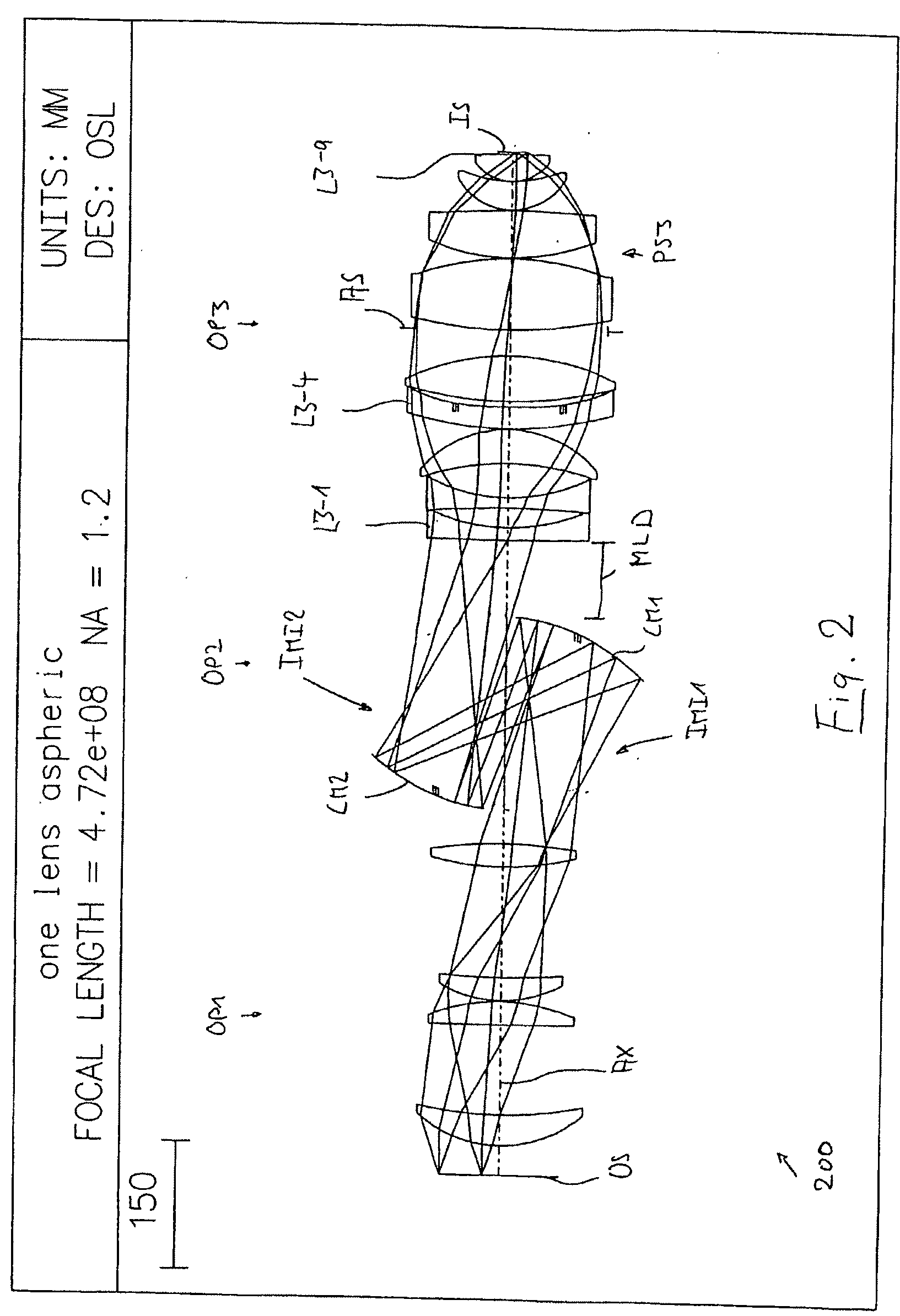
[0073]FIG. 2 shows a projection objective 200 having an all-spheric first objective part OP1 and only one aspheric lens L3-4 in third objective part OP3. An aperture stop AS is placed in the third objective part in the region of the pupil surface PS3 thereof. There is no need for a well-corrected position for an aperture stop in the first objective part OP1, which, in this case, consists of only four lenses, all lenses being spherical positive lenses. Thereby, a very simple and compact construction of the first objective part is obtained.

[0074]The projection objective 200 is designed as an immersion lens for λ=193 nm having an image side numerical aperture NA=1.20 when used in conjunction with a high index immersion fluid, e.g. pure water, between the exit surface of the objective and the image surface. The specification for this design is summarized in Table 2. The leftmost column lists the number of the refractive, reflective, or otherwise designated surface, the second column lis...

fourth embodiment

[0079]a projection objective 400 is shown in FIG. 4, the specification thereof is given in tables 4 and 4A. Similar to the embodiments of FIGS. 2 and 3, there is only one aspheric lens, namely positive meniscus lens L3-4 having an aspheric exit surface, in that system, placed in the third objective part OP3 in the region of largest beam diameter upstream of the aperture stop AS optically close to the pupil surface P3 of that objective part. The first objective part OP1 is all-spherical, having only one negative lens L1-4 in a sequence P-P-P-N-P, where “P” denotes a positive lens and “N” denotes a negative lens. From a construction point of view, a large axial distance between the vertex of the image side concave mirror CM1 and the first lens L3-1 of the third objective part OP3 is apparent, this distance MLD being more than 10% of the track length.

[0080]FIG. 5 shows a variant of the systems of FIGS. 3 and 4, where slight modifications predominantly in the first objective part OP1 we...


PUM


Abstract

A catadioptric projection objective for imaging a pattern provided in an object plane of the projection objective onto an image plane of the projection objective has a first, refractive objective part for imaging the pattern provided in the object plane into a first intermediate image; a second objective part including at least one concave mirror for imaging the first intermediate imaging into a second intermediate image; and a third, refractive objective part for imaging the second intermediate imaging onto the image plane; wherein the projection objective has a maximum lens diameter Dmax, a maximum image field height Y′, and an image side numerical aperture NA; wherein COMP1=Dmax / (Y′·NA2) and wherein the condition COMP1<10 holds.

Description

CROSS-REFERENCE TO RELATED APPLICATIONS[0001]This is a continuation-in-part application of International Application PCT / EP2005 / 007431, filed Jul. 8, 2005, which claims benefit of U.S. Provisional Applications 60 / 587,504, filed Jul. 14, 2004, 60 / 591,775, filed Jul. 27, 2004, 60 / 612,823, filed Sep. 24, 2004, 60 / 617,674, filed Oct. 13, 2004, 60 / 654,950, filed Feb. 23, 2005, and is further a continuation-in-part of U.S. application Ser. No. 11 / 035,103, filed Jan. 14, 2005, which claims benefit of the first four US Provisional Applications listed above as well as 60 / 536,248, filed Jan. 14, 2004 The disclosures of each of these related applications are hereby incorporated by reference into the present continuation-in-part application.BACKGROUND OF THE INVENTION[0002]1. Field of the Invention[0003]The invention relates to a catadioptric projection objective for imaging a pattern arranged in an object surface onto an image surface.[0004]2. Description of the Related Art[0005]Projection obj...

Claims


Application Information

Patent Timeline
Patent Type & Authority Applications(United States)
IPC IPC(8): G02B17/08
CPCG02B13/22G02B17/08G02B17/0812G02B17/0892G02B21/02G02B21/33G02B17/0816G03F7/70275G03F7/70341G03F7/70958G03F7/70966G02B17/0804G03F7/70225G02B13/16
Inventor SHAFER, DAVIDULRICH, WILHELMDODOC, AURELIANVON BUENAU, RUDOLFMANN, HANS-JUERGENEPPLE, ALEXANDERBEDER, SUSANNESINGER, WOLFGANG
Owner CARL ZEISS SMT GMBH
Why Eureka
Try Eureka