Catadioptric projection objective
- Summary
- Abstract
- Description
- Claims
- Application Information
AI Technical Summary
Benefits of technology
Problems solved by technology
Method used
Image
Examples
first embodiment
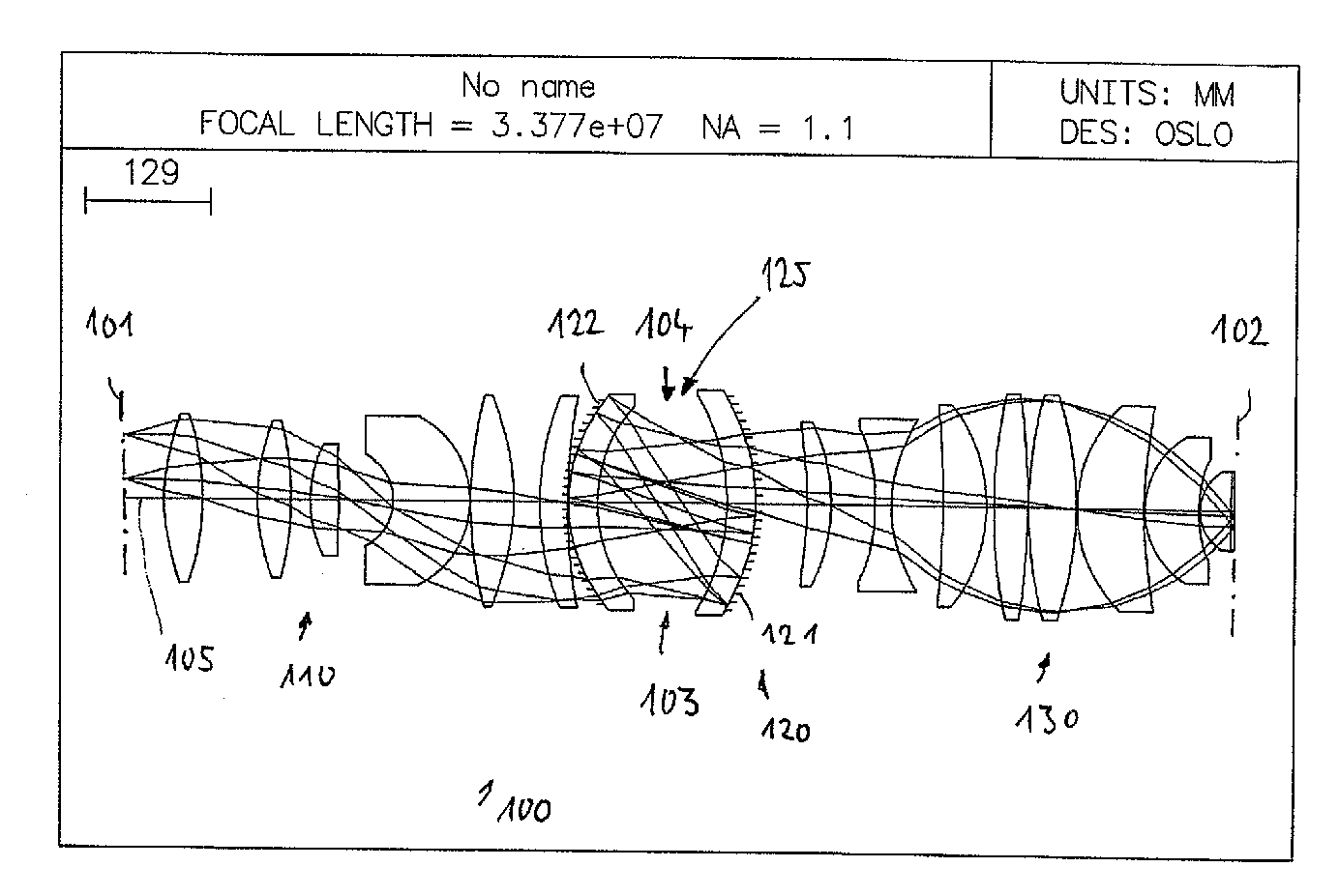
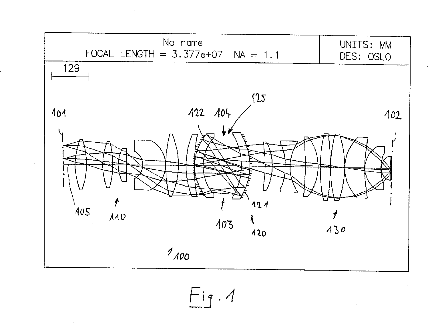
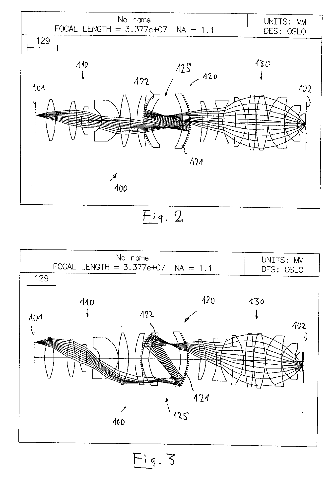
[0116]FIG. 1 shows a catadioptric projection lens 100 according to the invention designed for ca. 193 nm UV working wavelength. It is designed to project an image of a pattern on a reticle arranged in the object plane 101 into the image plane 102 on a reduced scale, for example, 4:1, while creating exactly two real intermediate images 103, 104. A first refractive objective part 110 is designed for imaging the pattern in the object plane into the first intermediate image 103 at an enlarged scale, a second, catadioptric objective part 120 images the first intermediate image 103 into the second intermediate image 104 at a magnification close to 1:1, and a third, refractive objective part 130 images the second intermediate image 104 onto the image plane 102 with a strong reduction ratio. The second objective part 120 comprises a first concave mirror 121 having the concave mirror surface facing the object side, and a second concave mirror 122 having the concave mirror surface facing the ...
second embodiment
[0127]In FIG. 4 a second embodiment is shown. Features or feature groups identical or similar in structure and / or function to those in FIG. 1 are denoted by similar numerals increased by 100.
[0128]The projection objective 200 is designed as an immersion lens for λ=193 nm having an image side numerical aperture NA=1.20 when used in conjunction with a high index immersion fluid, e.g. pure water, between the exit face of the objective and the image plane. The field size is 26·5.0 mm2. The specifications for this design are summarized in Table 4. The leftmost column lists the number of the refractive, reflective, or otherwise designated surface, the second column lists the radius, r, of that surface [mm], the third column lists the distance, d [mm], between that surface and the next surface, a parameter that is referred to as the “thickness” of the optical element, the fourth column lists the material employed for fabricating that optical element, and the fifth column lists the refracti...
third embodiment
[0138]In FIG. 10 a third embodiment is shown. Features or feature groups identical or similar in structure and / or function to those in FIG. 1 are denoted by similar numerals increased by 200. FIG. 11 represents a longitudinal sectional view of an embodiment designed on the basis depicted in FIG. 10.
[0139]The embodiment of a catadioptric projection objective 300 in FIG. 10 is similar to some of the above mentioned embodiments in that it comprises a first, refractive objective part 310 for creating a first intermediate image 303, a second, catoptric objective part 320 for creating a second intermediate image 304 from the first intermediate image, and a third, refractive objective part 330 for re-imaging the second intermediate image onto the image plane 302. The second objective part may include at least one lens such that it becomes a catadioptric objective part.
[0140]In contrast to the embodiments shown above, the second objective part 320 includes four reflective surfaces, namely t...
PUM
 Abstract
Description
Claims
Application Information
 - R&D
- Intellectual Property
- Life Sciences
- Materials
- Tech Scout
- Unparalleled Data Quality
- Higher Quality Content
- 60% Fewer Hallucinations
Browse by: Latest US Patents, China's latest patents, Technical Efficacy Thesaurus, Application Domain, Technology Topic, Popular Technical Reports.
© 2025 PatSnap. All rights reserved.Legal|Privacy policy|Modern Slavery Act Transparency Statement|Sitemap|About US| Contact US: help@patsnap.com


