Plasma display module

a display module and plasma technology, applied in the direction of identification means, electrical apparatus casings/cabinets/drawers, instruments, etc., can solve the problems of increasing the resistance of the line, increasing the length of the reference voltage line, and increasing the noise generated in the internal and external portions of the module, so as to improve the grounding structure and drive stably. , the effect of improving the process of constructing the plasma display modul

Inactive Publication Date: 2005-05-26
SAMSUNG SDI CO LTD
View PDF12 Cites 26 Cited by
  • Summary
  • Abstract
  • Description
  • Claims
  • Application Information

AI Technical Summary

Benefits of technology

[0012] It is therefore, an object of the present invention to provide a plasma display module having an improved grounding structure to be driven stably, and a improved process for constructing a plasma display module.

Problems solved by technology

Since the grounding of the connection cable is electrically connected through the circuit board however, the length of the reference voltage line increases, and accordingly, resistance of the line is increased and the line becomes vulnerable to noises generated in internal and external portions of the module.
Thus, the reference voltage can not be constantly maintained.
In addition, since the structure of grounding becomes more complex as the length of the reference voltage line is increased, the stability of the grounding is lowered and grounding defects may be created by external shock or vibration.

Method used


Image

  • Plasma display module
  • Plasma display module
  • Plasma display module

Examples


Embodiment Construction

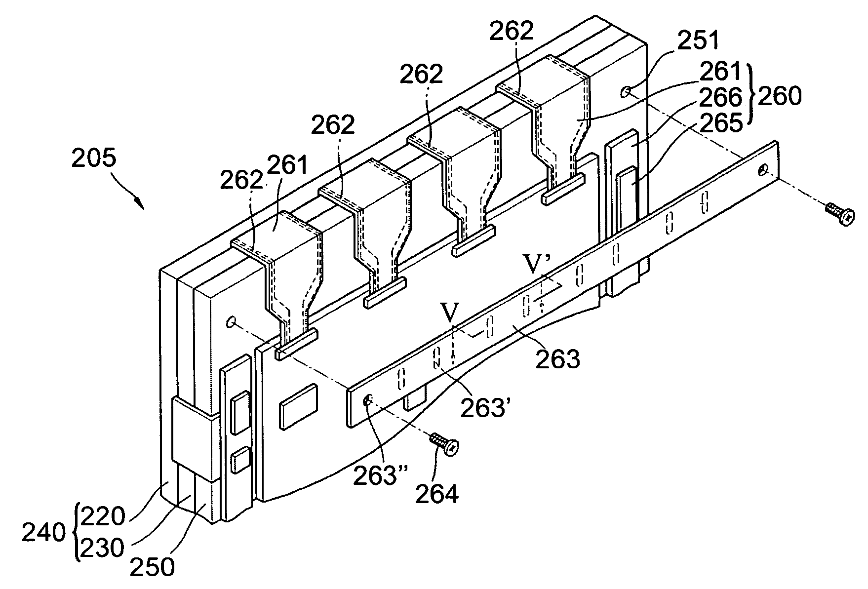
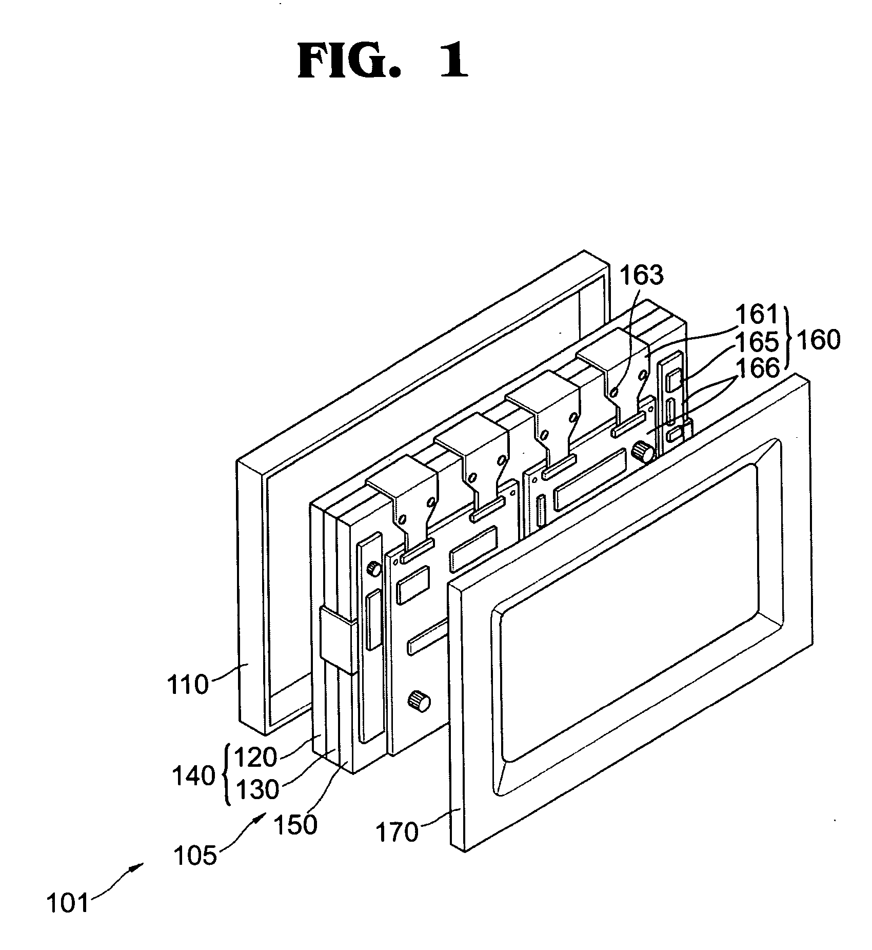
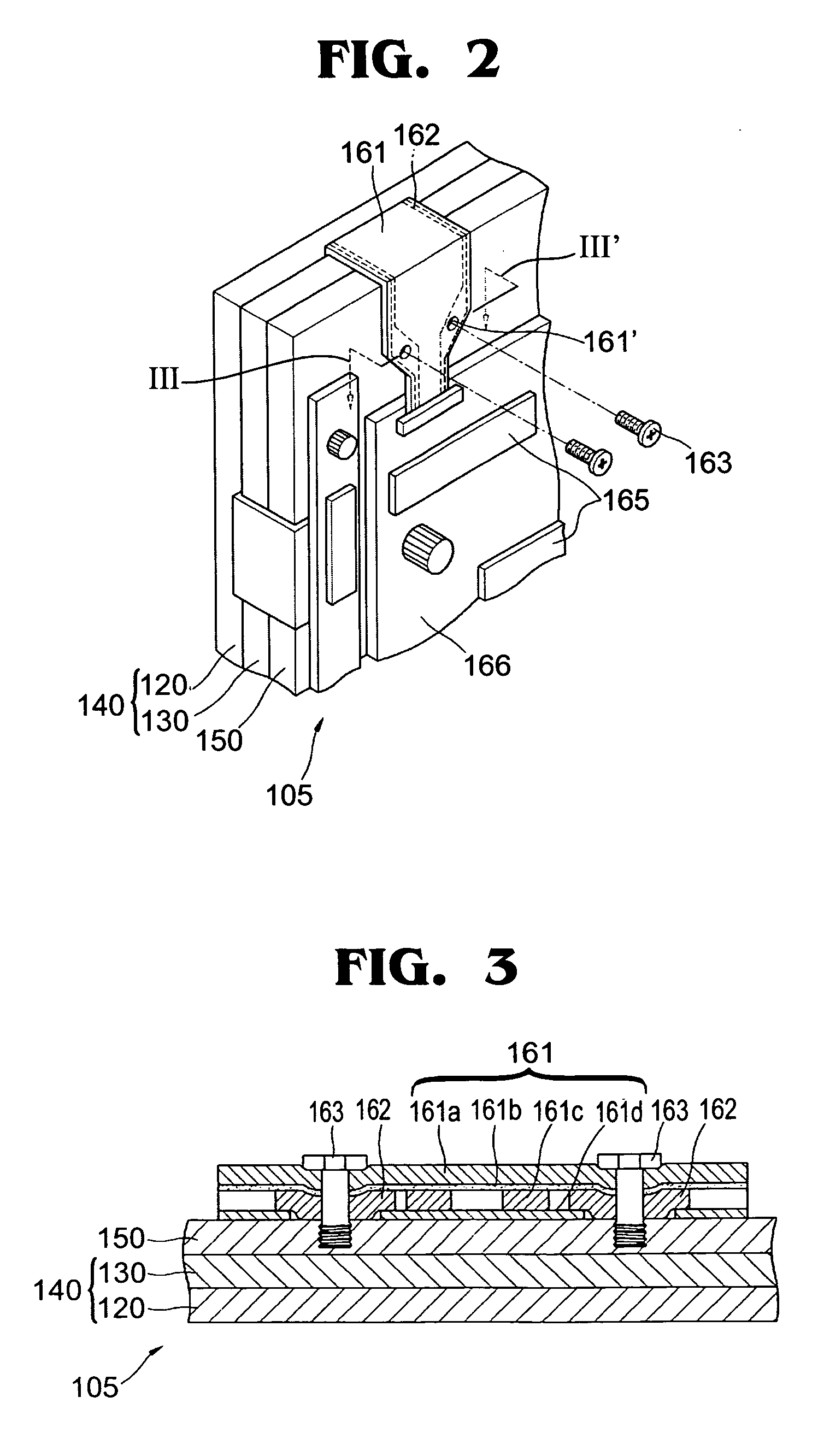
[0024]FIG. 1 is an exploded perspective view showing a plasma display apparatus including a plasma display module according to the present invention, and FIG. 2 is a perspective view showing the plasma display module shown in FIG. 1. In addition, FIG. 3 is a cross-sectional view showing the plasma display module taken along line III-III′ of FIG. 2.

[0025] Referring to FIG. 1 and FIG. 2 together, the plasma display module 105 of the present invention is surrounded by a front cabinet that forms bezel 110, and a back cover 170, to form a plasma display apparatus 101.

[0026] Plasma display module 105 includes a plasma display panel (PDP) 140, a chassis base 150, and a circuit unit 160. PDP 140 includes a front panel 120 and a back panel 130 that faces front panel 120. PDP 140 that is formed of a glass material that becomes an image display unit that forms an image through a discharge phenomenon, and a plurality of sustain electrode pairs (not shown) and a plurality of address electrodes...


PUM


Abstract

A plasma display module constructed with a chassis base; a plasma display panel supported by the chassis base in front of the chassis base to display an image; a circuit board on which a plurality of circuit devices that drive the plasma display panel are mounted, supported by the chassis base behind the chassis base; and a connection cable electrically connecting the circuit board and the plasma display panel, and directly grounded to the chassis base. Therefore, the module will be electrically stable when driven because of its grounding structure, and is suitable for providing images of high resolution.

Description

CLAIM OF PRIORITY [0001] This application makes reference to, incorporates the same herein, and claims all benefits accruing under 35 U.S.C. §119 from my application PLASMA DISPLAY MODULE filed with the Korean Intellectual Property Office on 16 Oct. 2003 and there duly assigned Ser. No. 2003-72148. BACKGROUND OF THE INVENTION [0002] 1. Field of the Invention [0003] The present invention relates to a plasma display module and, more particularly, to a plasma display module having an improved grounding structure. [0004] 2. Description of the Related Art [0005] A plasma display module is a flat panel display module that displays images using a gas discharge phenomenon, and is highlighted as a next generation flat panel display module that can substitute for a cathode ray tube (CRT) because a plasma display module has excellent display characteristics such as display capacity, brightness, contrast, residual image, and wide viewing angle. [0006] The plasma display module includes a plasma...

Claims


Application Information

Patent Timeline
Patent Type & Authority Applications(United States)
IPC IPC(8): G06F1/16H05K9/00G09F9/00G09F9/313H01J17/02H01J17/16H01J17/49H05K5/02
CPCH05K5/02H01J11/46H04N5/645H01J17/16
Inventor KIM, DAE-GYU
Owner SAMSUNG SDI CO LTD
Why Eureka
Try Eureka