Circuit module
a circuit module and circuit technology, applied in the field of circuit modules, can solve the problems of insufficient isolation between the first signal wiring line and the second signal wiring line, and achieve the effects of suppressing the leakage of signals, high isolation, and improving the structure of ground wiring lines
- Summary
- Abstract
- Description
- Claims
- Application Information
AI Technical Summary
Benefits of technology
Problems solved by technology
Method used
Image
Examples
first embodiment
[0047]—Circuit Module According to
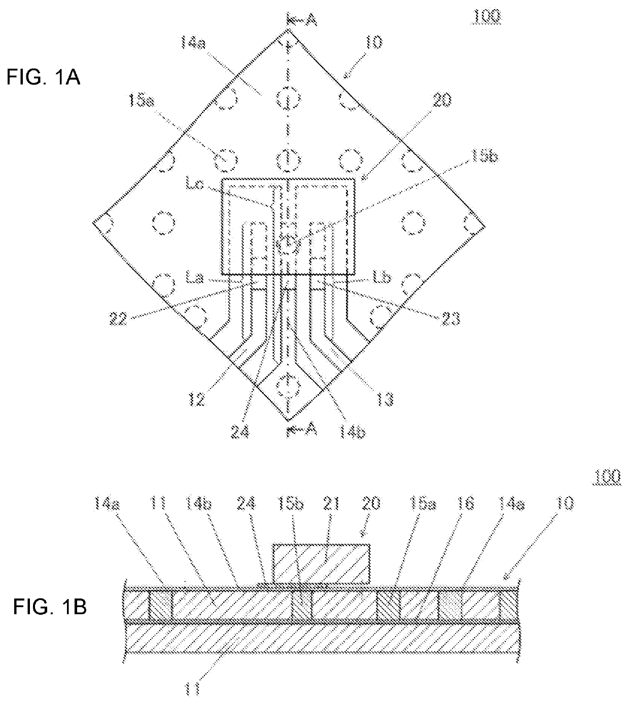
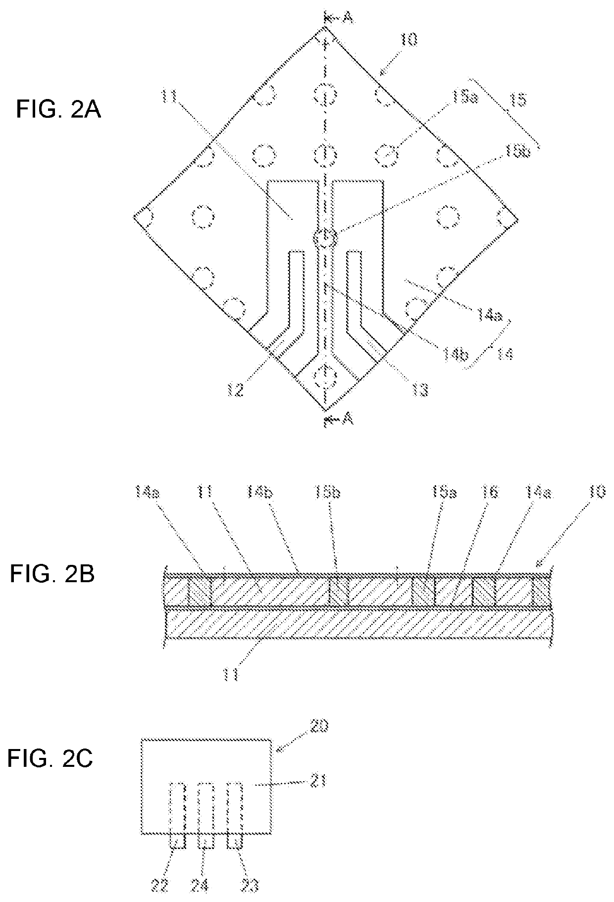
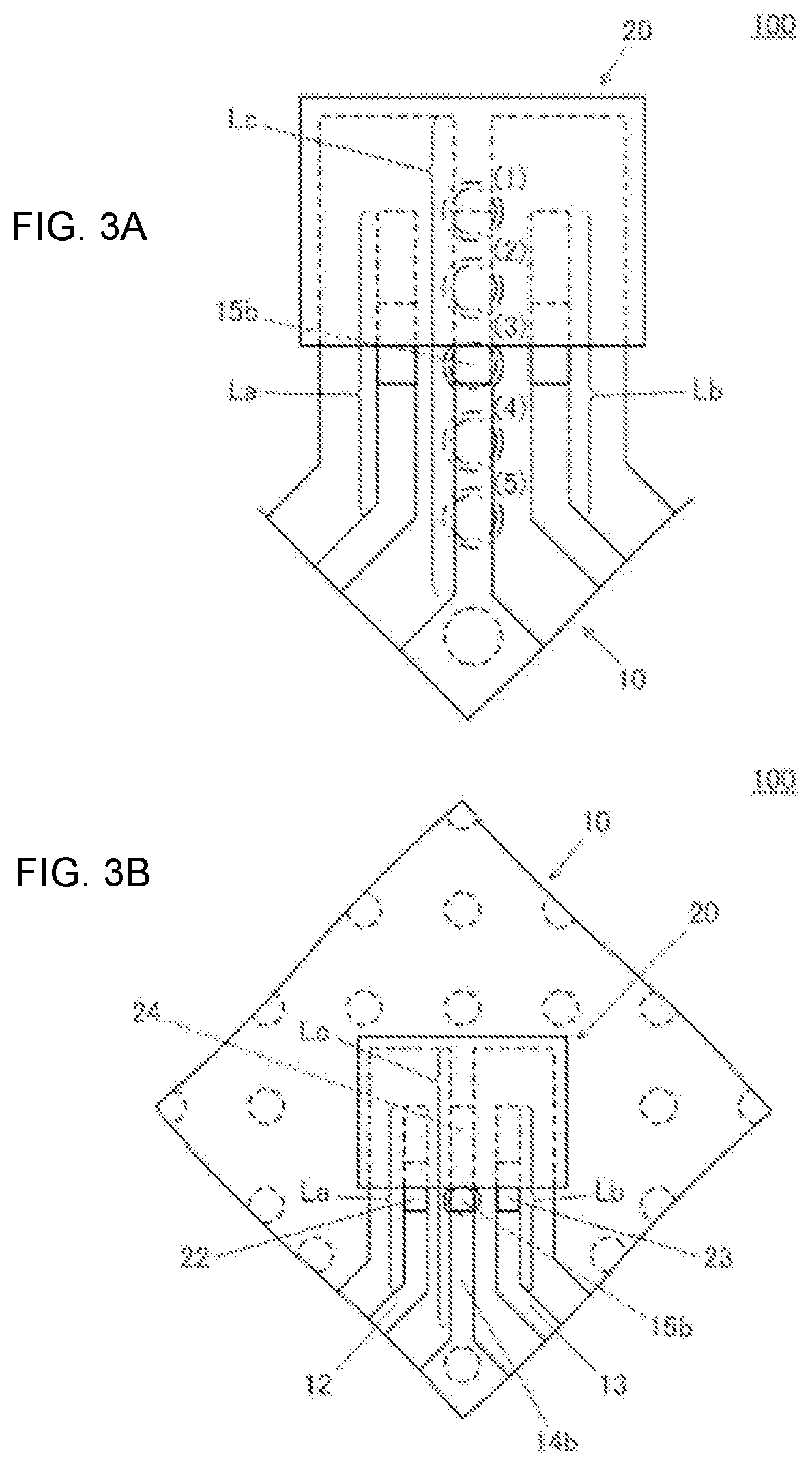
[0048]The structure of a circuit module according to the first embodiment of the present disclosure will be described with reference to FIGS. 1 and 2.
[0049]Each drawing is a schematic diagram and does not necessarily reflect the dimensions of actual products. In addition, the respective drawings do not necessarily reflect variations in the shapes of components that occur during manufacturing processes. That is, in the present specification, the drawings that will be referred to in the following description essentially illustrate the actual products even if there are differences between the drawings and the actual products.
[0050]FIGS. 1A and 1B are a top view and a cross-sectional view, respectively, of a circuit module according to the first embodiment of the present disclosure. FIG. 1A is a top view of a circuit module 100. FIG. 1B is a cross-sectional view of the circuit module 100 cut along a plane including line A-A illustrated in FIG. 1A. FIGS....
second embodiment
[0062]—Circuit Module According to
[0063]The structure of a circuit module according to the second embodiment of the present disclosure will be described with reference to FIG. 4.
[0064]FIG. 4 is a top view of a circuit module according to the second embodiment of the present disclosure. A circuit module 200 includes a circuit board 10A and an electronic component 20A. The circuit board 10A includes the insulating layer 11, the first signal conductor 12, the second signal conductor 13, a third signal conductor 17, a fourth signal conductor 18, the ground conductor 14, the via conductor 15, and the ground conductor layer 16. The electronic component 20A includes the component base body 21, the first signal terminal 22, the second signal terminal 23, a third signal terminal 26, a fourth signal terminal 27, the first ground terminal 24, a second ground terminal 25, a third ground terminal 28, and a fourth ground terminal 29.
[0065]The third signal conductor 17 and the fourth signal conduc...
third embodiment
[0085]—Circuit Module According to
[0086]The structure of a circuit module according to the third embodiment of the present disclosure will be described with reference to FIG. 9.
[0087]FIG. 9 is a top view of a circuit module according to the third embodiment of the present disclosure. A circuit module 400 includes a circuit board 10B and an electronic component 20A. The circuit board 10B is similar to the circuit board 10A illustrated in FIG. 4, and includes the insulating layer 11, the first signal conductor 12, the second signal conductor 13, the third signal conductor 17, the fourth signal conductor 18, the ground conductor 14, the via conductor 15, and the ground conductor layer 16. However, the ground conductor 14 does not include the fifth strip portion 14f. The first strip portion 14b and the third strip portion 14d are not connected. The second strip portion 14c and the fourth strip portion 14e are not connected. The electronic component 20A is the same as that illustrated in...
PUM
 Abstract
Description
Claims
Application Information
 - R&D
- Intellectual Property
- Life Sciences
- Materials
- Tech Scout
- Unparalleled Data Quality
- Higher Quality Content
- 60% Fewer Hallucinations
Browse by: Latest US Patents, China's latest patents, Technical Efficacy Thesaurus, Application Domain, Technology Topic, Popular Technical Reports.
© 2025 PatSnap. All rights reserved.Legal|Privacy policy|Modern Slavery Act Transparency Statement|Sitemap|About US| Contact US: help@patsnap.com


