Thermal solution for electronic devices

Active Publication Date: 2005-05-26
NEOGRAF SOLUTIONS LLC
View PDF17 Cites 49 Cited by
  • Summary
  • Abstract
  • Description
  • Claims
  • Application Information

AI Technical Summary

Benefits of technology

[0019] In another embodiment of the invention, the thermal solution can have a layer of aluminum or other isotropic conductor like copper laminated or coated thereon so as to be interposed between the thermal solution and the surface of the heat source to improve handleability and mechanical robustness of the thermal solution, as well as to modify the thermal transfer and EMI/RF shielding characteristics of the thermal solution. Likewise, a thermal interface material, such as a thermal grease or a graphite-based thermal interface like that described in International Patent Application No. PCT/US02/40238 and/or commercially available from Advanced Energy Technology Inc. of Lakewood, Ohio as its eGraf Hi-Therm™ line of products can be interposed between the thermal solution and the heat source to facilitate heat transfer between the heat source and the inventive thermal solution.
[0020] In addition, in order to improve mechanical robustness and handleability of the thermal solution, and potentially to further block or shield heat from being transmitted from the heat source to the external surface of the device or to other device components, a layer of a

Problems solved by technology

Due to the relatively low through-thickness thermal conductivity (or, put another way, high thermal anisotro

Method used


Image

  • Thermal solution for electronic devices
  • Thermal solution for electronic devices
  • Thermal solution for electronic devices

Examples


Example

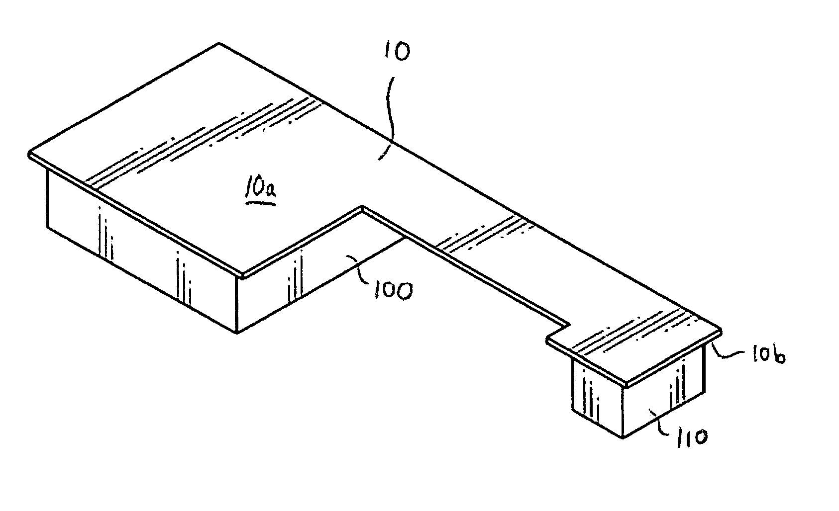
[0033] As noted, the inventive thermal solution is formed from sheets of compressed particles of exfoliated graphite, commonly known as flexible graphite. Graphite is a crystalline form of carbon comprising atoms covalently bonded in flat layered planes with weaker bonds between the planes. By treating particles of graphite, such as natural graphite flake, with an intercalant of, e.g. a solution of sulfuric and nitric acid, the crystal structure of the graphite reacts to form a compound of graphite and the intercalant. The treated particles of graphite are hereafter referred to as “particles of intercalated graphite.” Upon exposure to high temperature, the intercalant within the graphite decomposes and volatilizes, causing the particles of intercalated graphite to expand in dimension as much as about 80 or more times its original volume in an accordion-like fashion in the “c” direction, i.e. in the direction perpendicular to the crystalline planes of the graphite. The exfoliated gra...


PUM


Abstract

A thermal solution for an electronic device, which is positioned between a heat source and an external surface of the electronic device and/or another component of the electronic device, where the thermal solution facilitates heat dissipation from the heat source while shielding the external surface and/or second component from the heat generated by the heat source.

Description

TECHNICAL FIELD [0001] The present invention relates to a thermal solution capable of managing the heat from a heat source such as a component of an electronic device, so as to dissipate heat generated by the heat source while mediating the effects of the heat on users of the device and other device components. BACKGROUND OF THE INVENTION [0002] With the development of more and more sophisticated electronic devices, including those capable of increasing processing speeds and higher frequencies, having smaller size and more complicated power requirements, and exhibiting other technological advances, such as microprocessors and integrated circuits in electronic and electrical components, high capacity and response memory components such as hard drives, electromagnetic sources such as light bulbs in digital projectors, as well as in other devices such as high power optical devices, relatively extreme temperatures can be generated. However, microprocessors, integrated circuits and other...

Claims


Application Information

Patent Timeline
IPC IPC(8): G06F1/18H05K9/00G06F1/20H01L23/373H01L23/552H05K7/20
CPCG06F1/182G06F1/203H01L23/373H01L23/552H01L2924/0002H01L2924/09701H01L2924/00H05K7/20H05K9/00
Inventor SMALC, MARTIN DAVIDSHIVES, GARY D.REYNOLDS, ROBERT ANDERSON III
Owner NEOGRAF SOLUTIONS LLC
Why Eureka
Try Eureka