power conversion device

A technology for power conversion devices and power conversion circuits, which is applied in the direction of output power conversion devices, circuits, electrical components, etc., can solve problems such as poor heat dissipation efficiency, achieve uniform temperature, improve heat sink efficiency, and promote heat transfer effects

Active Publication Date: 2016-07-13
HITACHI LTD
View PDF5 Cites 0 Cited by
  • Summary
  • Abstract
  • Description
  • Claims
  • Application Information

AI Technical Summary

Problems solved by technology

However, the transfer of heat from the heat receiving block to the heat dissipation part is only affected by the heat conduction inside the heat dissipation part, and there is a problem of poor heat dissipation efficiency compared with the heat transfer of the heat pipe.

Method used


Image

  • power conversion device
  • power conversion device
  • power conversion device

Examples


Embodiment 1

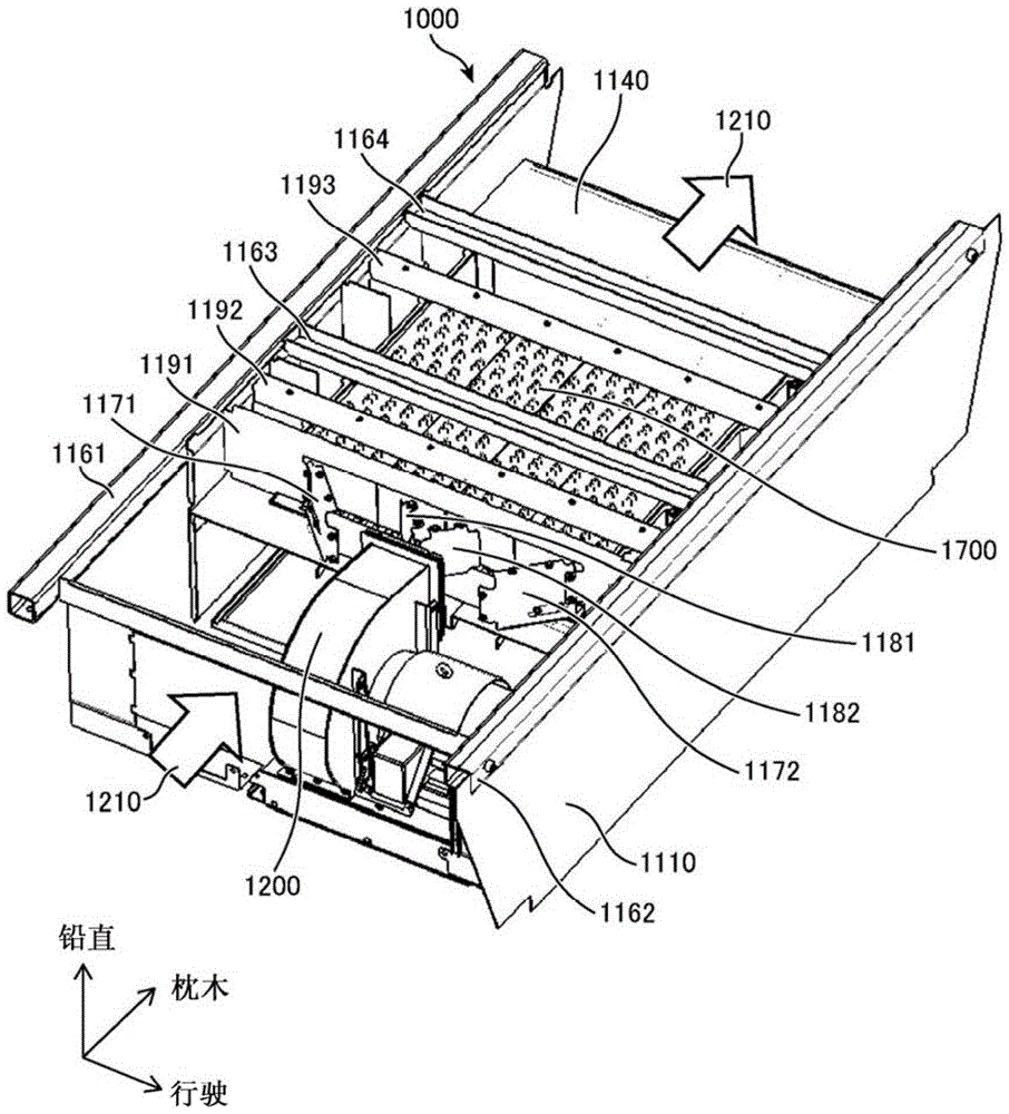
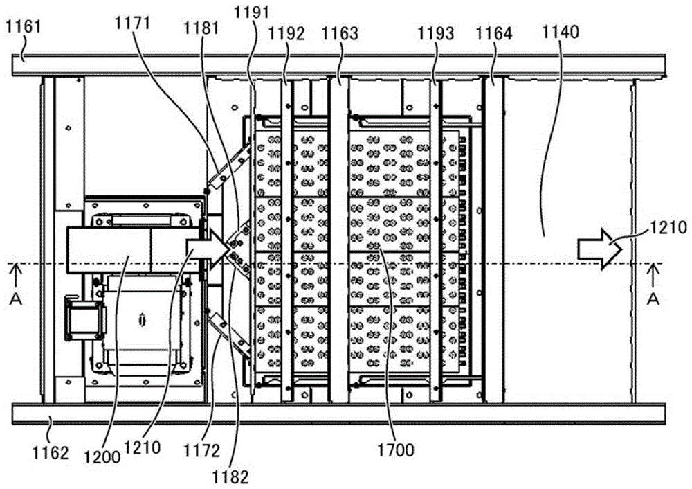
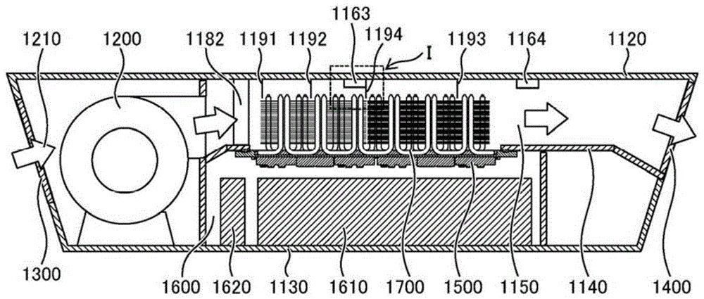
[0108] Hereinafter, it will describe in detail with reference to drawings. figure 1 A perspective view showing the overall structure of the power conversion device according to the first embodiment of the present invention, figure 2 express figure 1 top view of image 3 express figure 2 A-A cutaway view.

[0109] The power conversion device 1000 is composed of a side plate 1110 , a top plate 1120 , and a bottom plate 1130 . In addition, sleeper direction beams 1161 and 1162 and travel direction beams 1163 and 1164 are provided on the upper surface of the power conversion device 1000 to secure the strength of the power conversion device 1000 . A ventilation path bottom plate 1140 is provided between the top plate 1120 and the bottom plate 1130 . The space surrounded by the side plate 1110 , the top plate 1120 , and the ventilation path bottom plate 1140 is the ventilation path 1150 , and the cooling air 1210 flows through the ventilation path 1150 . In addition, the s...

Embodiment 2

[0141] Figure 22 The arrangement of the heat pipes in the power conversion device according to the second embodiment of the present invention is shown. In the second embodiment, the L-shaped heat pipe 1730 on the windward side is omitted, and compared with the first embodiment, the number of heat pipes is reduced. Other structures are the same as in Embodiment 1. When the temperature on the upwind side is lower than the temperature on the downwind side, by reducing the number of heat pipes on the upwind side in this way, the ventilation resistance between the heat sinks can be further reduced, so that the semiconductor element group 1500 can be effectively cooled, and the heat dissipation can be further reduced. manufacturing cost.

Embodiment 3

[0143] Figure 23 The configuration of the heat sink in the power conversion device according to the third embodiment of the present invention is shown. In the third embodiment, the cooling fins 1750 are not divided into the windward side and the leeward side as in the first embodiment, but the cooling fins 1750 are provided with the same pitch and the same number of sheets. Other structures are the same as in Embodiment 1. When it is desired to lower the temperature on the windward side, such a configuration can improve the cooling performance on the windward side, and thus effectively cool the semiconductor element group 1500 on the windward side.


PUM


Abstract

The present invention discloses a power conversion apparatus, which can inhibit the freezing of refrigerant even if the temperature of cooling wind is below a freezing point of the refrigerant inside a heat pipe, and can balance the influence of heat distribution change of semiconductor elements caused by different operation conditions or influence caused by temperature rising of the cooling wind, therefore cooling can be done effectively. The power conversion apparatus is characterized in that a plurality of semiconductor elements comprise a plurality of first IGBT modules that have enlarged heat volume in regenerative operation, a plurality of second IGBT modules that have enlarged heat volume in power operation, and a plurality of clamping diode modules that have smaller heat than the IGBT modules. Semiconductor elements that have same heat are arranged in an orthogonal direction with the flow of the cooling wind, and the clamping diode modules are set between the first IGBT modules and the second IGBT modules in the flow direction of the cooling wind.

Description

technical field [0001] The present invention relates to a power conversion device for electric railway vehicles including a current switch circuit for controlling a motor. Background technique [0002] Electric railway vehicles are equipped with power conversion devices such as converters and inverters in order to control electric motors that drive the vehicles. These power conversion devices perform power conversion by performing switching control at high frequencies using semiconductor elements such as IGBT (Insulated Gate Bipolar Transistor) and GTO (Gate Turn Off Thyristor). In order to reduce noise generated during this switching operation, a three-level switching circuit that outputs three-level currents of positive, negative, and neutral is commonly used. [0003] In semiconductor elements, heat is generated during power-on and switching control. If the temperature of the semiconductor element becomes high due to this heat, the conversion efficiency may decrease or t...

Claims


Application Information

Patent Timeline
Patent Type & Authority Patents(China)
IPC IPC(8): H02M7/00H05K7/20
CPCH01L2924/0002
Inventor 安田阳介舟越砂穗佐川哲田中健寺门秀一冈安刚佐藤忠则鲸冈真一郎
Owner HITACHI LTD
Why Eureka
Try Eureka