

Refrigeration cycle device
A refrigeration cycle and control device technology, applied in the direction of refrigerators, refrigeration components, refrigeration and liquefaction, etc., can solve the problems such as the decline in the importance of volume control technology, achieve the effect of improving the coefficient of performance, reducing pressure loss, and improving heat transfer
- Summary
- Abstract
- Description
- Claims
- Application Information
AI Technical Summary
Problems solved by technology
Method used
Image

Examples
Embodiment approach 1
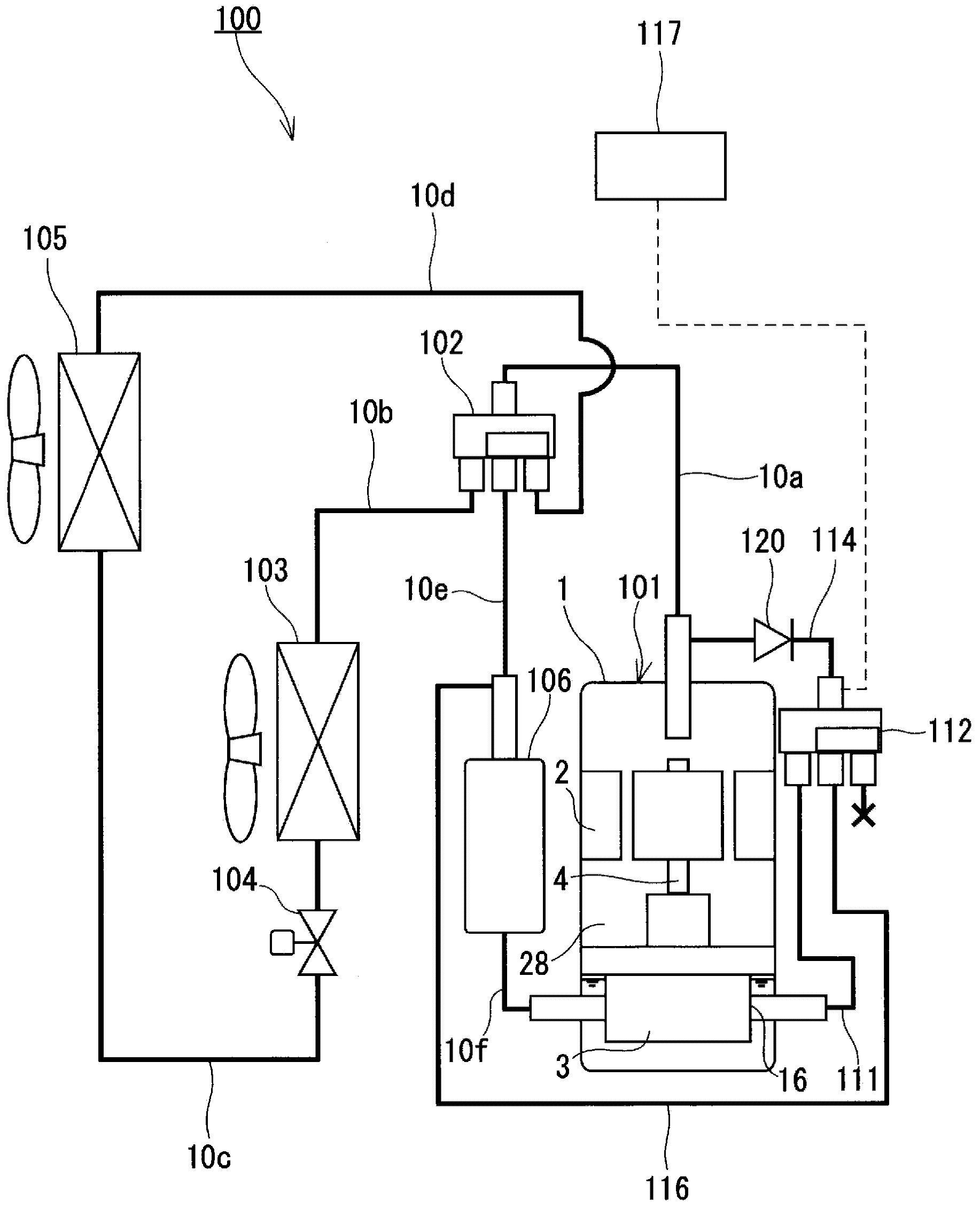
[0085] Such as figure 1 As shown, the refrigeration cycle apparatus 100 of this embodiment includes a displacement control compressor 101 , a first four-way valve 102 , a first heat exchanger 103 , an expansion mechanism 104 , a second heat exchanger 105 , and a heat accumulator 106 . These components are connected to each other through flow paths 10a to 10f to form a refrigerant circuit. The flow paths 10a to 10f are each constituted by refrigerant piping.
[0086] The first heat exchanger 103 is a radiator that cools the refrigerant compressed by the compressor 101 or an evaporator that heats the refrigerant expanded by the expansion mechanism 104 . The second heat exchanger 105 is an evaporator when the first heat exchanger 103 is a radiator, and is a radiator when the first heat exchanger 103 is an evaporator. The expansion mechanism 104 has a function of expanding the refrigerant cooled by the radiator, and a typical expansion mechanism 104 is constituted by an expansi...
Deformed example 1
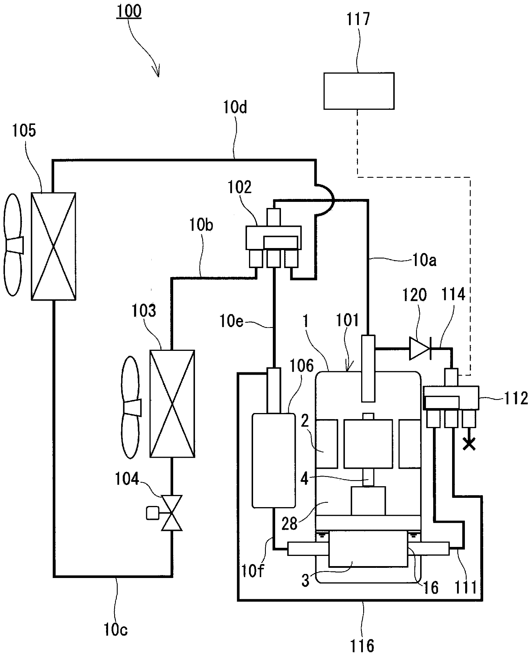
[0111] Such as Figure 4 As shown, the refrigeration cycle apparatus 200 according to Modification 1 differs from the refrigeration cycle apparatus 100 of Embodiment 1 in that it further includes a safety valve circuit 221 . Hereinafter, the same reference numerals are assigned to the same components in the previous embodiment or modified example as in the subsequent embodiment or modified example, and description thereof will be omitted.
[0112] The high-pressure introduction path 114 has a first portion 114a between the check valve 120 and the second four-way valve 112 (flow path switching portion), and a second portion 114b between the check valve 120 and the flow path 10a (discharge path). The safety valve circuit 221 has one end connected to the first part 114 a and the other end connected to the second part 114 b or the flow path 10 a so as to bypass the check valve 120 . When the difference between the pressure of the first part 114a and the pressure of the second par...
Deformed example 2
[0115] Such as Figure 5 As shown, the refrigeration cycle apparatus 300 according to Modification 2 differs from the first embodiment in that it includes a compressor 301 having a different structure from the compressor 101 of the first embodiment.
[0116] Such as Figure 6 As shown, the compressor 301 is equipped with the airtight container 1, the motor 2, and the compression mechanism 30, and this compressor 301 is a multi-cylinder rotary compressor (two cylinders in this modification). The refrigerant compressed by the compression mechanism 30 is introduced into the flow path 10 a via the internal space 28 of the airtight container 1 . The compression mechanism 30 has a first compression chamber 40 , a second compression chamber 42 , an intermediate chamber 69 , a first discharge port 67 , a first discharge valve 63 , a second discharge port 71 , a second discharge valve 73 , and a bypass discharge port. 65 and the bypass discharge valve 61.
[0117] The flow path 10 a...
PUM
 Abstract
Description
Claims
Application Information