Method and instrument for microscopy

a microscopy and instrument technology, applied in the field of illuminating objects, can solve the problems of disruptive interference phenomena, inflexible use of known illuminating devices, and low luminance of laser-based illuminating devices and illuminating methods, and achieves universal usability and flexibility, minimize interference phenomena, and high luminance

Inactive Publication Date: 2005-05-26
LEICA MICROSYSTEMS CMS GMBH
View PDF34 Cites 6 Cited by
  • Summary
  • Abstract
  • Description
  • Claims
  • Application Information

AI Technical Summary

Benefits of technology

[0018] It is an object of the invention to provide a method for illuminating an object which is universally usable and flexible, furthermore provides a broad wavelength spectrum together with a high luminance, and also minimizes interference phenomena.

Problems solved by technology

Owing to this limitation of the working spectrum, the known illuminating devices are not flexibly usable.
Laser-based illuminating devices and illuminating methods also have the disadvantage that, owing to the high coherence of the laser light, disruptive interference phenomena, such as e.g. diffraction rings and Newton's rings, occur.

Method used


Image

  • Method and instrument for microscopy
  • Method and instrument for microscopy
  • Method and instrument for microscopy

Examples


Embodiment Construction

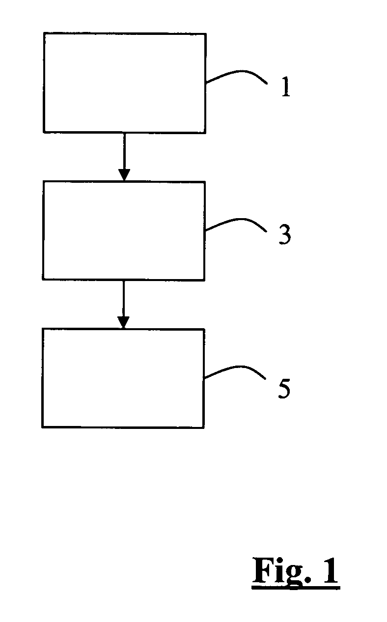
[0056]FIG. 1 shows a flow chart of the method according to the invention. In a first step, the light from a laser is injected 1 into a microstructured optical element that spectrally broadens the light. In this case, the light is guided to the microstructured optical element, for example with the aid of mirrors, and is preferably focused onto the microstructured optical element using a variable lens. In a second step, the light emerging from the microstructured optical element is shaped 3 to form an illumination light beam, preferably with the aid of optical means which are configured as lens systems. In a further step, the illumination light beam is directed 5 onto the object.

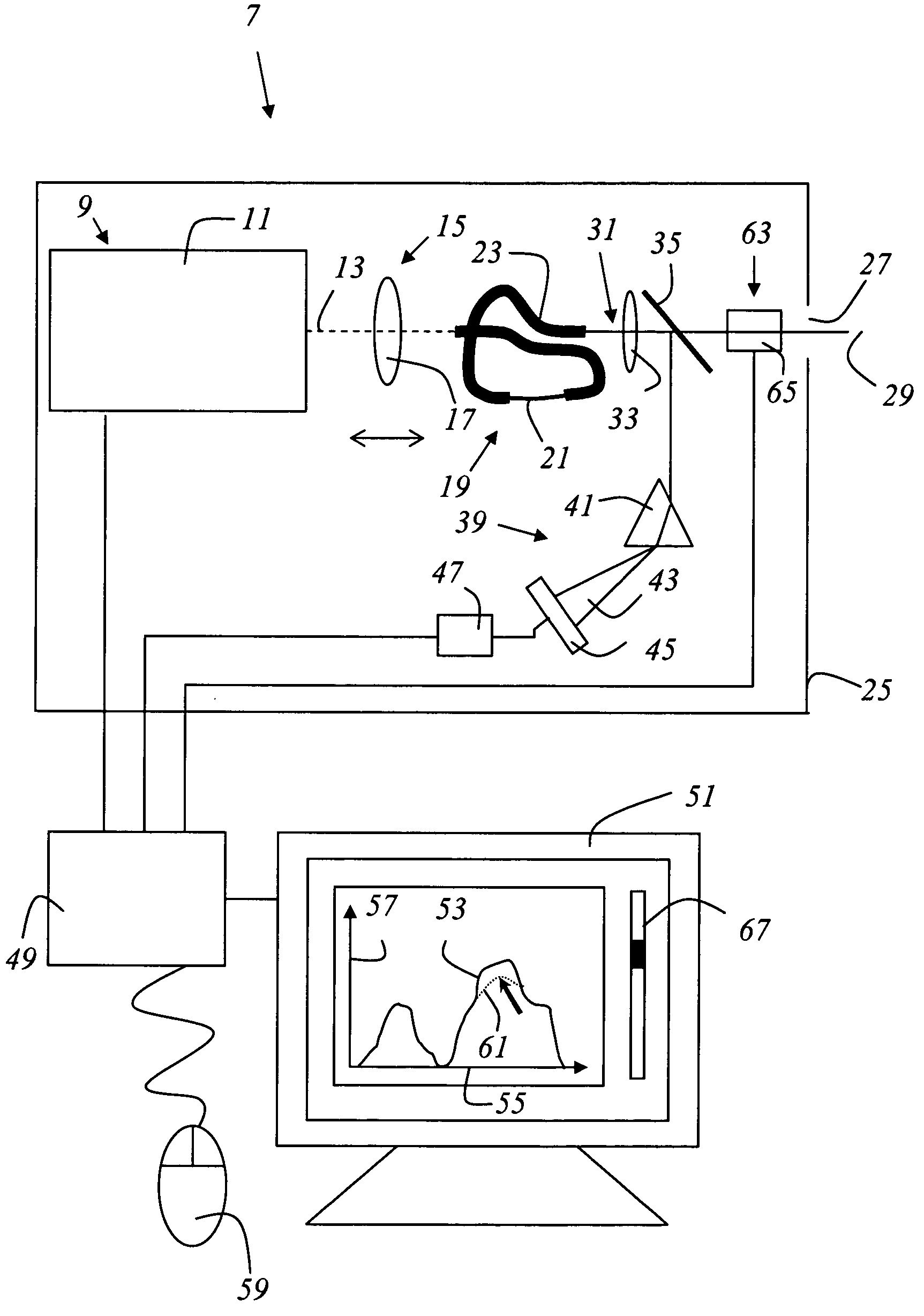
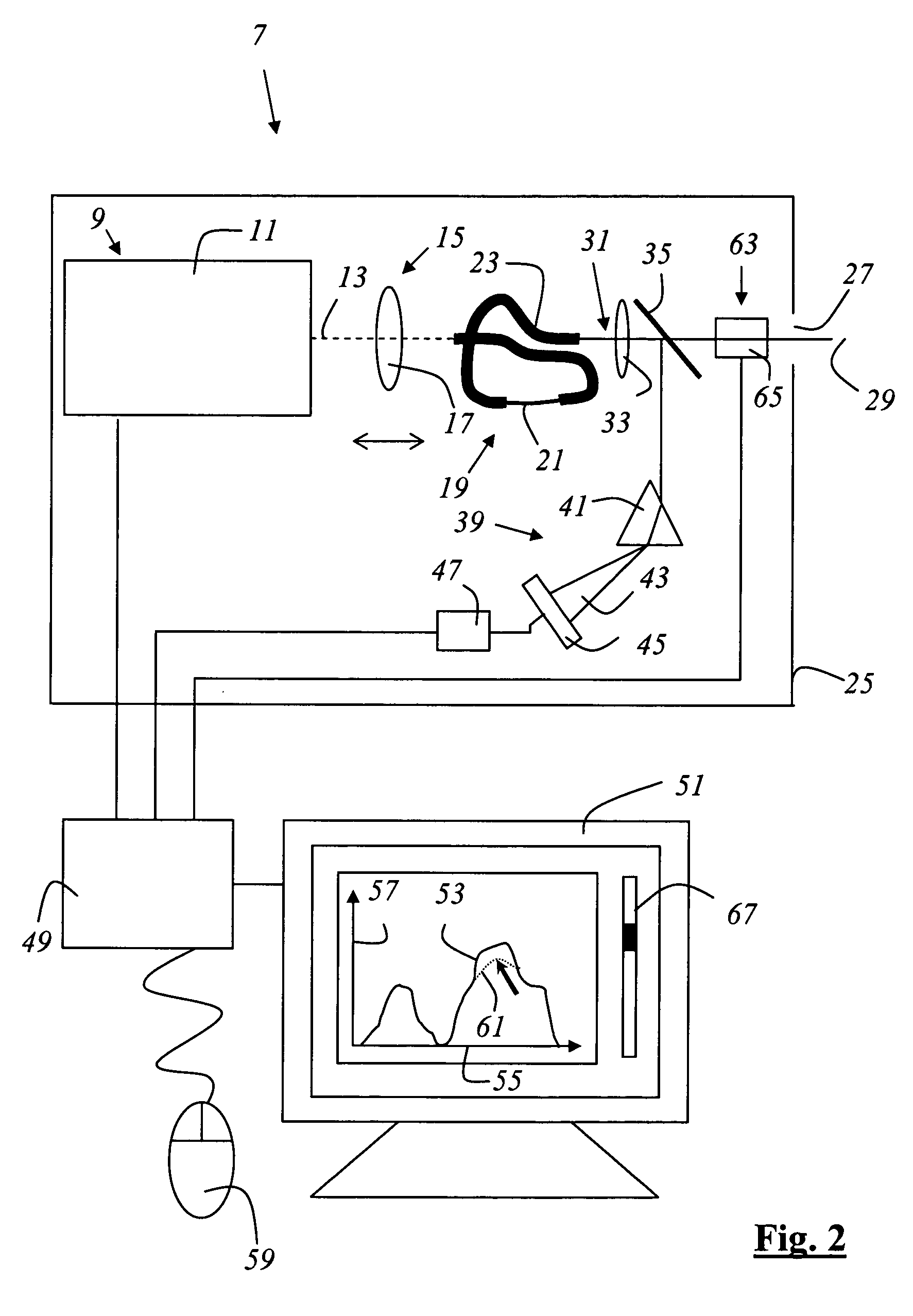
[0057]FIG. 2 shows an illuminating instrument 7 which contains a laser 9 that is embodied as a mode-locked Ti:sapphire laser 11 and emits a light beam 13, which is shown in dashes, with the property of an optical pulse train. The width of the light pulses is approximately 100 fs with a repetition rate of appr...


PUM


Abstract

A microscope includes a light source that emits an illuminating light beam for illumination of a specimen, a beam splitter separating measuring light out of the illuminating light beam, and an apparatus for determining the light power level of the illuminating light beam. The apparatus for determining the light power level of the illuminating light beam receives the measuring light and includes an apparatus for simultaneous color-selective detection of the measuring light.

Description

CROSS REFERENCE TO RELATED APPLICATIONS [0001] This invention is a continuation of U.S. patent application Ser. No. 09 / 881,049, which claims priority to German patent applications 100 30 013.8 and 101 15 487.9 and 101 15 589.1 and 101 15 486.0 and 101 15 488.7 and 101 15 509.3 and 101 15 577.8 and 101 15 590.5, all of which are hereby incorporated by reference herein. [0002] This application refers to U.S. patent application Ser. No. 09 / 881,048, entitled “ARRANGEMENT FOR STUDYING MICROSCOPIC PREPARATIONS WITH A SCANNING MICROSCOPE”, which is incorporated herewith. [0003] This application refers to U.S. patent application Ser. No. 09 / 881,046, entitled “ILLUMINATING DEVICE AND MICROSCOPE”, which is hereby incorporated by reference herein. [0004] This application refers to U.S. patent application Ser. No. 09 / 880,825, entitled “ENTANGLED-PHOTON MICROSCOPE AND CONFOCAL MICROSCOPE”, which is hereby incorporated by reference herein. [0005] This application refers to U.S. patent application...

Claims


Application Information

Patent Timeline
Patent Type & Authority Applications(United States)
IPC IPC(8): G02B6/02G02B6/122G02B6/255G02B21/00G02B21/06G02B27/00H01S3/00H01S3/16
CPCB82Y20/00Y10S385/901G02B6/02371G02B6/02376G02B6/1225G02B6/2552G02B21/002G02B21/0024G02B21/0032G02B21/0056G02B21/0064G02B21/0068G02B21/0076G02B21/008G02B21/06H01S3/005H01S3/1625H01S3/1636G02B6/02366
Inventor BIRK, HOLGERSTORZ, RAFAELENGELHARDT, JOHANNMOELLMANN, KYRA
Owner LEICA MICROSYSTEMS CMS GMBH
Why Eureka
Try Eureka