Transfer roll engagement method for minimizing media induced motion quality disturbances

a technology of media induced motion and engagement method, which is applied in the field of drums, can solve problems such as motion quality problems, image mis-registration, or other undesirable effects, and transient rotational disturbance of the drum

Inactive Publication Date: 2005-05-26
XEROX CORP
View PDF6 Cites 44 Cited by
  • Summary
  • Abstract
  • Description
  • Claims
  • Application Information

AI Technical Summary

Problems solved by technology

The addition and removal of such a load in such a period of time may cause the velocity of the imaging drum to deviate, resulting in a transient rotational disturbance of the drum.
The imaging drum servo control system may be insufficient to accommodate these velocity deviations, resulting in image mis-registration, or other undesirable effects, referred to as motion quality problems.
The imaging must be completed before beginning the transfer process because of the motion quality problems associated with engaging the transfer roller with the imaging drum after the image has been formed on the imaging drum.
As a result, productivity is limited by performing the imaging and transferring operations in series.

Method used


Image

  • Transfer roll engagement method for minimizing media induced motion quality disturbances
  • Transfer roll engagement method for minimizing media induced motion quality disturbances
  • Transfer roll engagement method for minimizing media induced motion quality disturbances

Examples


Embodiment Construction

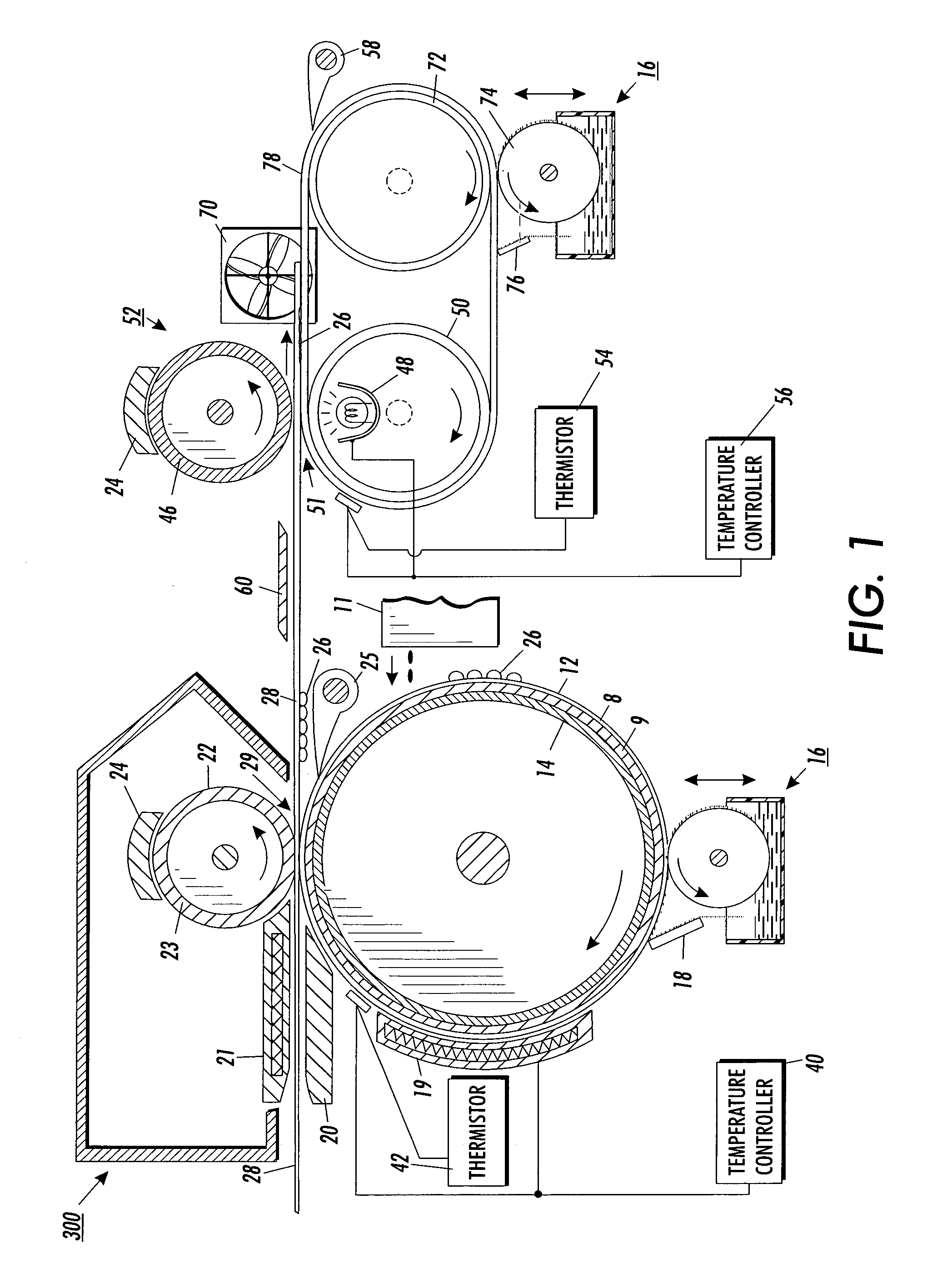
[0013]FIG. 1 discloses a diagrammatical illustration of an imaging apparatus 10 of the present invention for applying a two-step transfix process whereby a hot melt ink is printed onto an transfer surface for transference to a receiving substrate and then transported through a fuser for post fusing. Referring to FIG. 1 wherein like numerals refer to like or corresponding parts throughout, there is shown a printhead 11 having ink jets supported by appropriate housing and support elements (not shown) for either stationary or moving utilization to deposit ink onto an intermediate transfer surface 12. The ink utilized is preferably initially in solid form and then changed to a molten state by the application of heat energy to raise the temperature from about 85 degrees to about 150 degrees centigrade. Elevated temperatures above this range will cause degradation or chemical breakdown of the ink. The molten ink is then applied in raster fashion from ink jets in the printhead 11 to the in...


PUM

PropertyMeasurementUnit
temperatureaaaaaaaaaa

Abstract

A method of maintaining a rotational velocity of an imaging drum during engagement with a transfer roll in an image producing device including: forming a nip to transfer an image from the imaging drum to media when the imaging drum is in engagement with the transfer roll; maintaining a substantially constant imaging drum rotational velocity mode during engagement with the transfer roll; sensing a lead edge of portion of the media prior to entering the nip; augmenting torque assist to increase the torque of the transfer roll when the media is in the nip for a defined period; and resuming the substantially constant imaging drum rotational velocity mode while a second portion of the media is in the nip.

Description

FIELD OF INVENTION [0001] The present invention relates generally to a drum for fixing an ink image on a receiving medium and, more particularly, to a system and method for reducing motion quality defects while printing or copying an image. BACKGROUND OF THE INVENTION [0002] For printing in a solid-ink printer, a common method of applying droplets of ink onto a piece of paper is to directly print the image onto the paper, i.e., a process known as direct printing. Ink jet printing systems utilizing intermediate transfer ink jet recording methods, such as that disclosed in U.S. Pat. No. 5,389,958 entitled IMAGING PROCESS and assigned to the assignee of the present application is an example of an indirect or offset printing architecture that utilizes phase change ink. A release agent application defining an intermediate transfer surface is applied by a wicking pad that is housed within an applicator apparatus. Prior to imaging, the applicator is raised into contact with the rotating dr...

Claims


Application Information

Patent Timeline
Patent Type & Authority Applications(United States)
IPC IPC(8): B41F16/00B41J2/005B41J2/01B41J11/00B41M5/00H04N1/00H04N1/047
CPCB41J2/0057B41J2/17593H04N1/0473H04N1/00745H04N1/00681
Inventor CALAMITA, JAMES P.COSTANZA, DANIEL W.
Owner XEROX CORP
Why Eureka
Try Eureka