CMP polishing heads retaining ring groove design for microscratch reduction

a technology polishing head, which is applied in the field of retaining ring groove design of cmp head, can solve the problems of micro-scratches formed on the substrate, and achieve the effect of reducing repetition

Inactive Publication Date: 2005-05-26
CHARTERED SEMICONDUCTOR MANUFACTURING +1
View PDF12 Cites 45 Cited by
  • Summary
  • Abstract
  • Description
  • Claims
  • Application Information

AI Technical Summary

Benefits of technology

[0032] The above advantages and features are of representative embodiments only, and are not exhaustive and/or exclusive. They are presented only to assist in understanding the invention. It should be understood that they are not representative of all the inventions defined by the claims, to be considered limitations on the invention as defined by the claims, or limitations on equivalents to the claims. For instance, some of these advantages may be mutually contradictory, in that they cannot be simultaneously present in a single embodiment. Similarly, some advantages are

Problems solved by technology

A problem of current chemical-mechanical polish (CMP) machines and proce

Method used


Image

  • CMP polishing heads retaining ring groove design for microscratch reduction
  • CMP polishing heads retaining ring groove design for microscratch reduction
  • CMP polishing heads retaining ring groove design for microscratch reduction

Examples


Embodiment Construction

Introduction

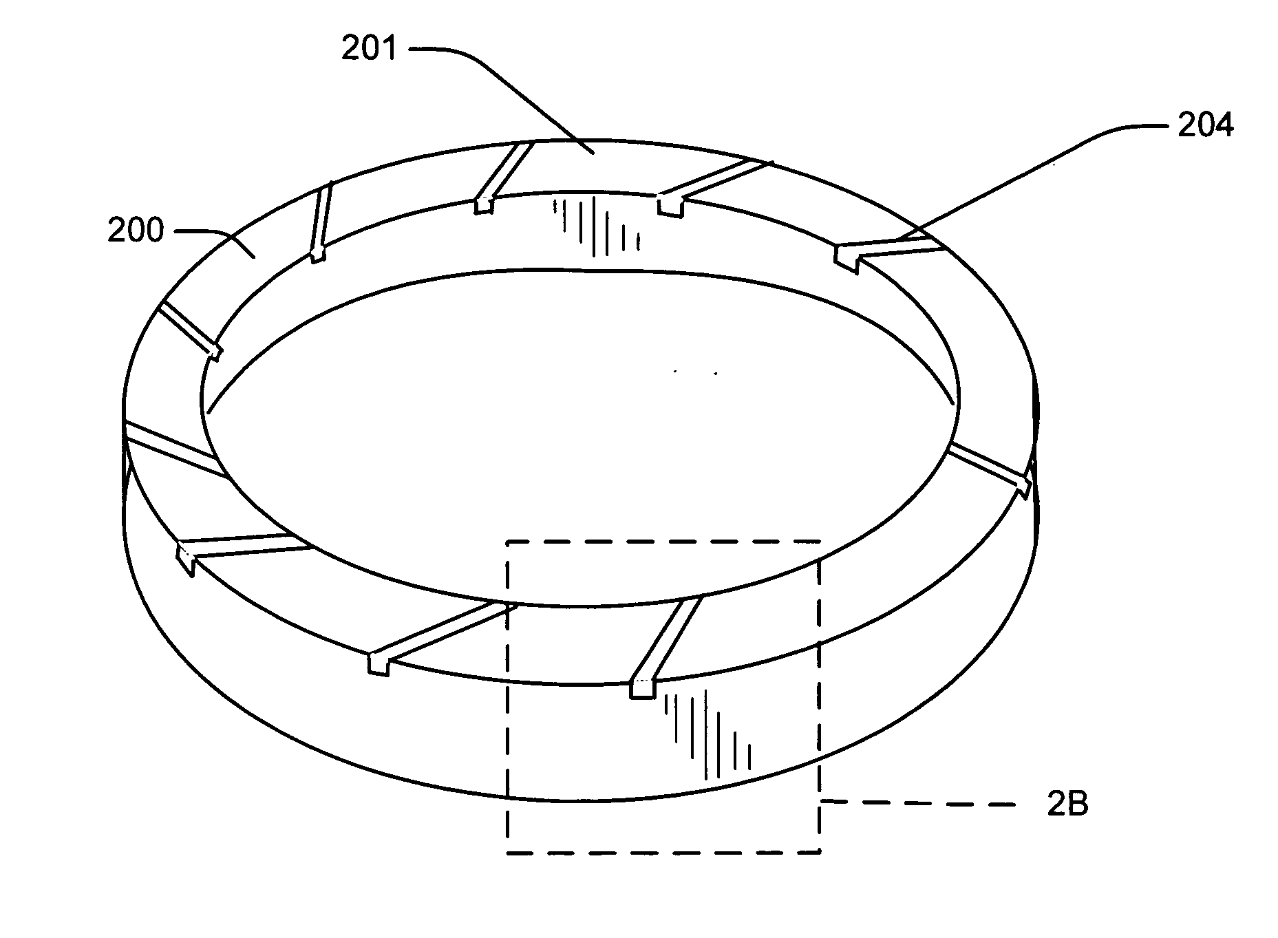
[0049] Referring now to the drawings and more particularly to FIGS. 2A, 2B, and 2C, there is shown a retaining ring 200 over which the aspects of the present invention are an improvement. It is to be understood in this regard that no portion of FIGS. 2A, 2B and 2C is admitted to be prior art as to the present invention. Rather, this these diagrams are an effort to provide an improved understanding of some of the problems that are overcome by the aspects of the invention.

[0050]FIG. 2A is perspective view of a retaining ring 200 having rectangular shaped grooves 204. The ring has a lower surface 201 (polishing surface or pad side surface) that in operation faces the polish pad.

[0051]FIG. 2B is a close up perspective view a groove 204 that has non-curved corners or edges in the a retaining ring 200.

[0052]FIG. 2C is a cross sectional view of a groove 204 that has slurry particles or other debris 208 that cause the problems as discovered by the inventors.

[0053] Microscr...


PUM

PropertyMeasurementUnit
Radiusaaaaaaaaaa
Radiusaaaaaaaaaa
Widthaaaaaaaaaa

Abstract

A chemical-mechanical polish (CMP) machine and fabrication process using the same. The CMP machine has a CMP retaining ring comprising: an inner peripheral surface; an outer peripheral surface; a lower surface adapted to contact and depress an upper surface of a polishing pad during chemical mechanical polishing of a lower surface of a substrate. The substrate is contained within the inner peripheral surface of the retaining ring during chemical mechanical polishing. At least a groove on the lower surface of the retaining ring. At least a portion of the groove has a rounded contour. In an aspect, the groove has a semicircle profile. In another aspect, the groove has a semicircle profile and a curved top corner profile at adjacent to the lower surface of the retaining ring. The retaining ring with a curved portion of groove reduces the accumulation of dried slurry in the groove and thus reduces micro-scratches.

Description

BACKGROUND OF INVENTION [0001] 1) Field of the Invention [0002] Embodiments of this invention relate to Chemical Mechanical Polishing (CMP) methods and machines, and particularly to retaining ring designs for CMP heads and more particularly to retaining ring designs with curved grooves for reducing microscatches on semiconductor structures. [0003] 2) Description of the Related Art [0004] In semiconductor fabrications, the chemical-mechanical polish (CMP) technique is widely used for the global planarization of semiconductor wafers that are used for the fabrication of VLSI (very large-scale integration) and ULSI (ultra large-scale integration) integrated circuits. [0005]FIGS. 1A and 1B are schematic diagrams showing a conventional CMP machine. The CMP machine comprises a polishing table 10 on which a polishing pad 12 is layered, a polishing head 14 for holding a semiconductor wafer 16 in position, and a nozzle 18 for applying a mass of slurry to the semiconductor wafer 16 during the ...

Claims


Application Information

Patent Timeline
IPC IPC(8): B24B37/04
CPCB24B37/32
Inventor CHEN, FENGLIM, CING GIELEONG, LUP SANWANG, SIM KIT
Owner CHARTERED SEMICONDUCTOR MANUFACTURING
Why Eureka
Try Eureka