Method and device for digital-to-RF conversion
a digital-to-rf converter and conversion method technology, applied in the field of digital-to-analog converters, can solve the problems of high-performance analog elements, limited flexibility of rf transmitters, and high sampling frequency of rf generation
- Summary
- Abstract
- Description
- Claims
- Application Information
AI Technical Summary
Benefits of technology
Problems solved by technology
Method used
Image
Examples
Embodiment Construction
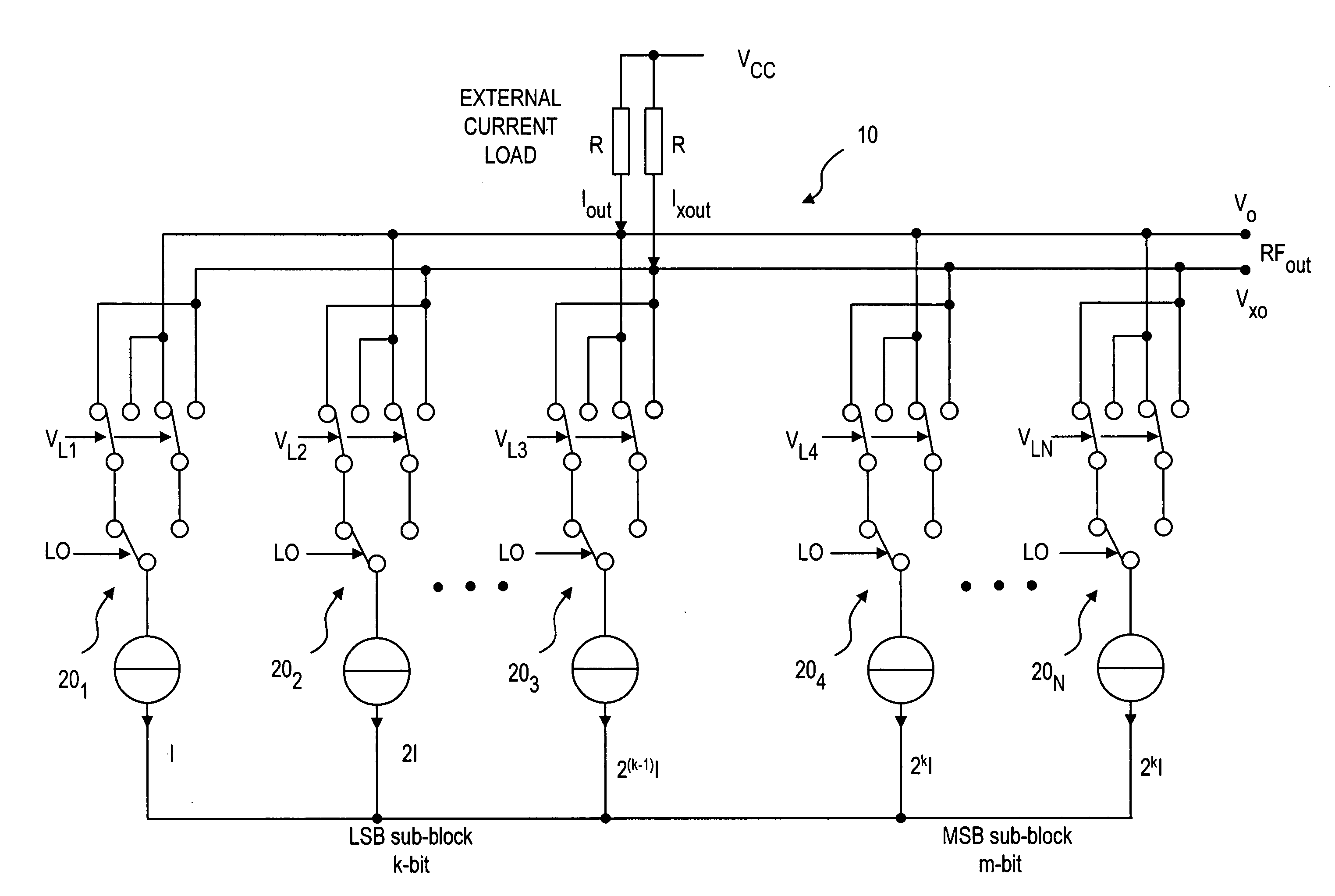
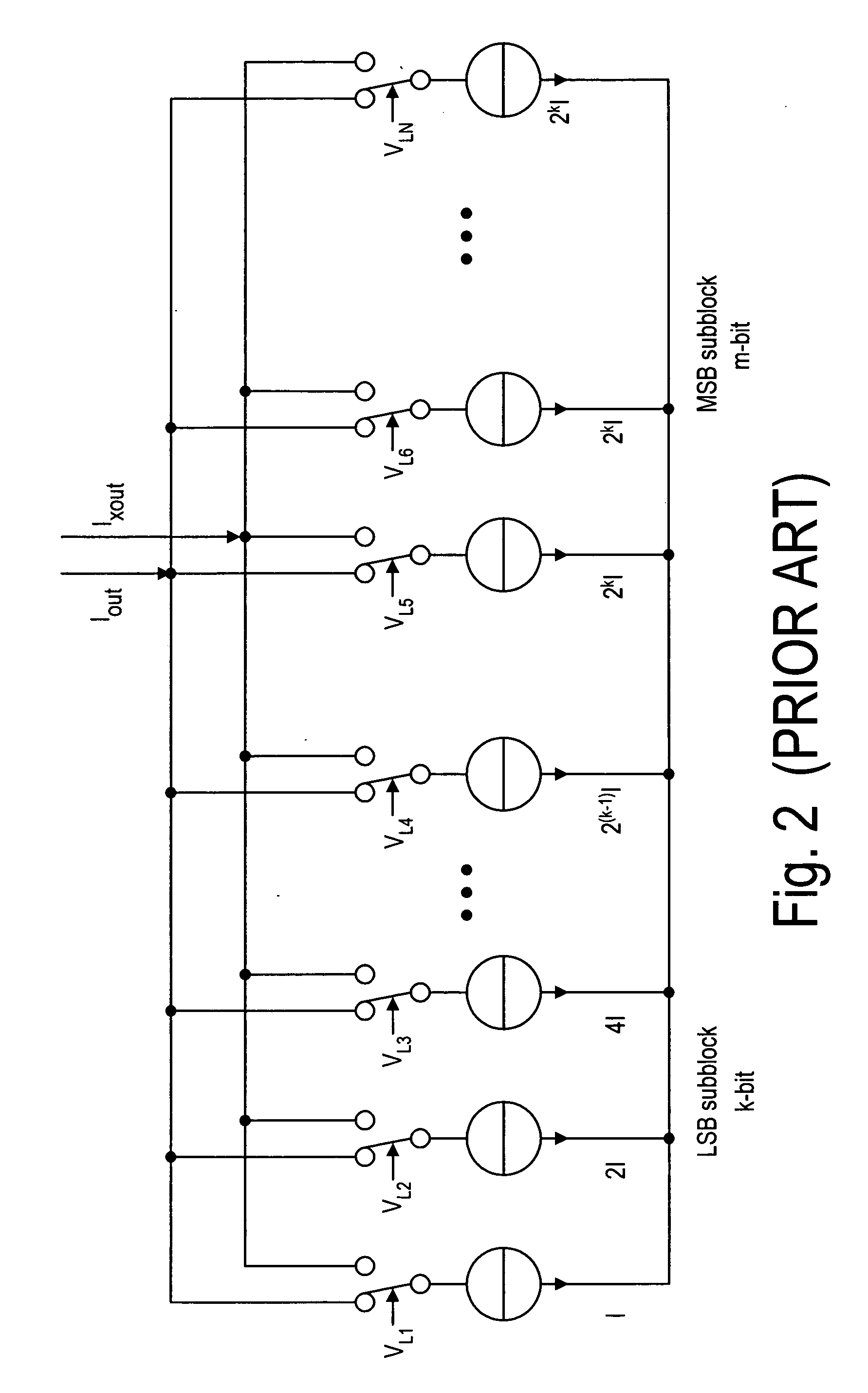
[0035] The Digital-to-RF-converter, according to the present invention, combines the D / A conversion function and the upconversion function by a carrier (LO), which can be RF or IF. As shown in FIG. 4, the Digital-to-RF-converter 10 comprises a plurality of parallel unit cells 201, 202, . . . , 20N, . . . . The upconverter 10 has a segmented configuration, including an LSB sub-block and an MSB sub-block. The current in the LSB sub-block is generated with parallel binary weighted units, whereas the current in the MSB sub-block is generated in a set of unary coded cells. The unary coding can be also used in the LSB sub-block. As with the convention D / A converter shown in FIG. 1, the number of the unary coded cells in the MSB sub-block in the Digital-to-RF-converter 10 is also 2m−1, where m is the number of bits in MSB sub-block. The Digital-to-RF-converter 10 has two differential current paths for conveying differential currents Iout and Ixout, so that the modulated output signal, RFou...
PUM
 Abstract
Description
Claims
Application Information
 - R&D
- Intellectual Property
- Life Sciences
- Materials
- Tech Scout
- Unparalleled Data Quality
- Higher Quality Content
- 60% Fewer Hallucinations
Browse by: Latest US Patents, China's latest patents, Technical Efficacy Thesaurus, Application Domain, Technology Topic, Popular Technical Reports.
© 2025 PatSnap. All rights reserved.Legal|Privacy policy|Modern Slavery Act Transparency Statement|Sitemap|About US| Contact US: help@patsnap.com


