
Arthroscopic tissue scaffold delivery device

a delivery device and tissue technology, applied in the field of surgical tools and devices for delivering tissue implants, can solve the problems of no acceptable way to arthroscopically deliver the scaffold without and no convenient method for delivering the tissue-loaded scaffold through a cannula to the defect site, etc., to achieve the effect of not reducing the pressure at the injury si

Active Publication Date: 2005-05-26
DEPUY SYNTHES PROD INC
View PDF59 Cites 161 Cited by
  • Summary
  • Abstract
  • Description
  • Claims
  • Application Information

AI Technical Summary

Benefits of technology

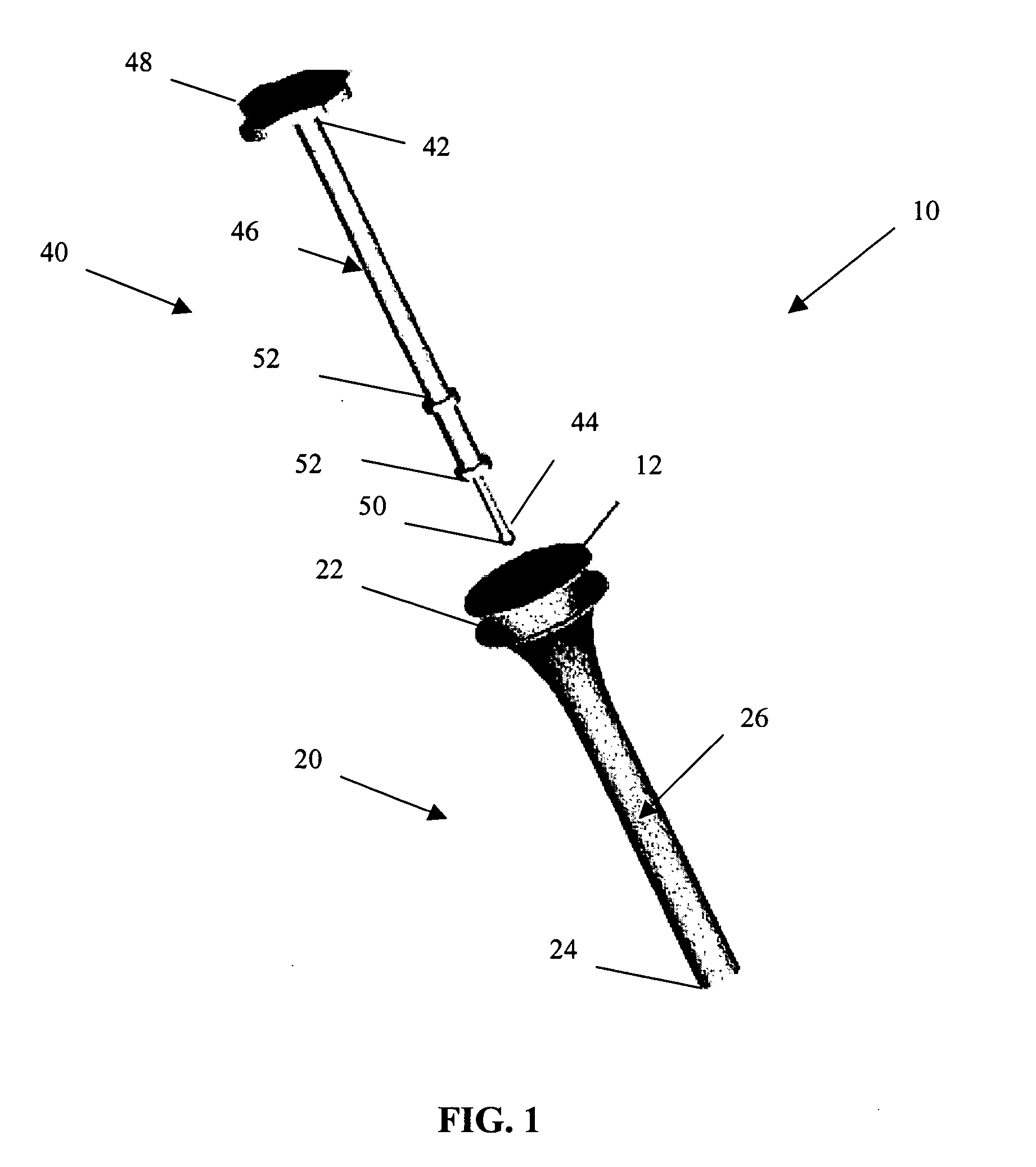
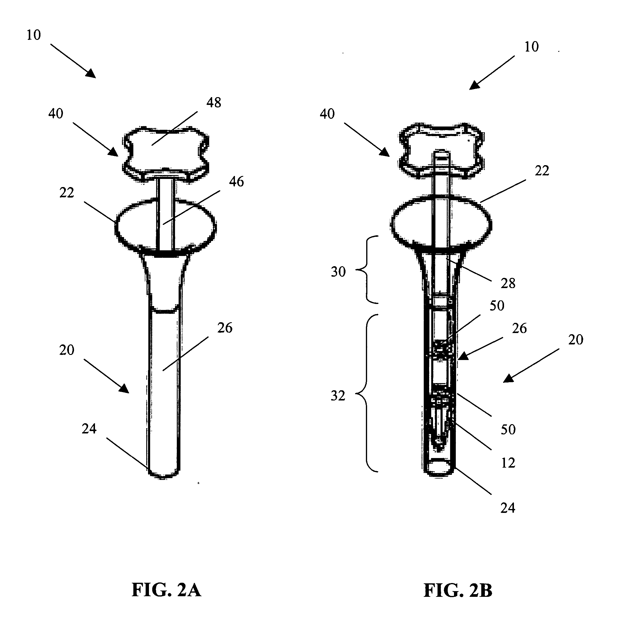
[0006] The passageway of the hollow, elongate body includes a first, flared portion that gradually extends into a second, tubular portion. Prior to delivery, the tissue scaffold can be held inside the insertion tube at the first, flared portion until the insertion rod is placed on the scaffold and urged distally. The force of the tip of the insertion rod against the tissue scaffold moves the scaffold through the passageway and out the distal end of the insertion tube. The gradual taper of the passageway allows the implant to be delivered without incurring damage in the process. Due to the small diameter of the insertion tube, the tissue scaffold can be arthroscopically delivered without reducing the pressure at the implantation site.

Problems solved by technology

Although a fully arthroscopic procedure for delivering a tissue-loaded scaffold to a defect site would be advantageous because of its minimally invasive nature and reduced side effects, there is presently no convenient method for delivering the tissue-loaded scaffolds through a cannula to the defect site without the risk of damaging the scaffold in the process.
Moreover, where it is necessary to deliver the scaffold to a defect in a joint, there is currently no acceptable way to arthroscopically deliver the scaffold without reducing the pressure inside the joint.

Method used


Image

  • Arthroscopic tissue scaffold delivery device
  • Arthroscopic tissue scaffold delivery device
  • Arthroscopic tissue scaffold delivery device

Examples


Embodiment Construction

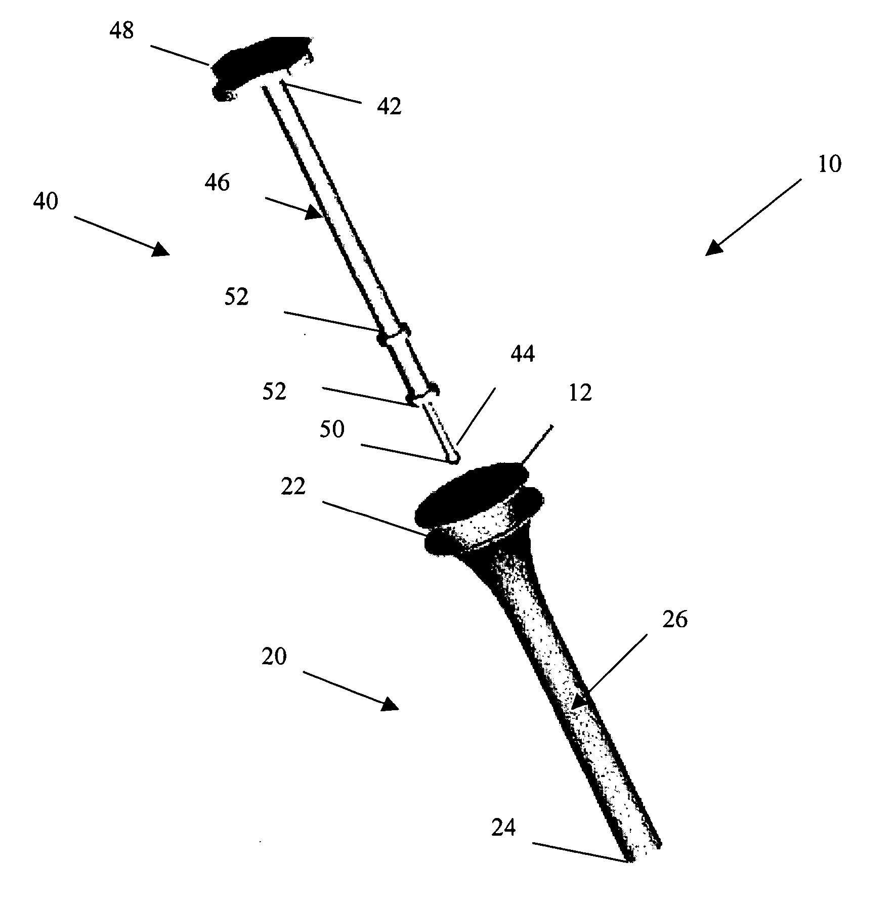
[0011] Turning now to the drawings and particularly to FIG. 1, a delivery system 10 for delivering a tissue scaffold 12 in accordance with the present invention is shown. The delivery system 10 comprises two main components. The first component is an insertion tube 20 and the second component is an insertion rod 40. The insertion tube 20 is defined by a flared proximal end 22 and a distal end 24. Extending between these ends 22, 24 is a hollow, elongate body 26. As shown in FIG. 2B, the hollow, elongate body 26 defines a passageway 28 comprising a first, flared portion 30 that extends into a second, tubular portion 32. The first, flared portion 30 can have a curved taper in order to provide a smooth transition between the two portions 30, 32 and to avoid damage to the tissue scaffold 12 during its delivery. The first, flared portion 30 can be integral with the second, tubular portion 32. Alternatively, the first, flared portion 30 can be provided as a separate component which is the...


PUM


Abstract

A small diameter delivery device capable of delivering a tissue loaded scaffold arthroscopically to a tissue defect or injury site without reducing the pressure at the injury site is provided. The scaffold delivery device of the present invention comprises a plunger system that includes two main components: an insertion tube and an insertion rod. The insertion tube has a flared proximal end for holding a tissue scaffold prior to delivery. An elongate, hollow body extends from the flared proximal end to a distal end of the insertion tube, and defines a passageway that extends through the body for delivery of the tissue scaffold. The insertion rod has an elongate body that extends into a handle at a proximal end and a tip at a distal end. The insertion rod is configured to be removably disposed within the insertion tube for sliding along the passageway to effect delivery of the tissue scaffold through the insertion tube.

Description

FIELD OF THE INVENTION [0001] This invention relates to surgical tools and devices for delivering a tissue implant. More particularly, this invention relates to a delivery device for arthroscopically delivering a tissue scaffold. BACKGROUND [0002] Injuries to soft tissue, such as cartilage, skin, muscle, bone, tendon, and ligament where the tissue has been injured or traumatized frequently require surgical intervention to repair the damage and facilitate healing. Such surgical repairs can include suturing or otherwise repairing the damaged tissue with known medical devices, augmenting the damaged tissue with other tissue, using an implant, a graft or any combination of these techniques. [0003] One common technique for repairing diseased or injured tissue is to implant a tissue scaffold at the defect site, either alone or along with cultured and amplified cells. In the past, such scaffolds have consisted mostly of two- or three-dimensional porous scaffolds that allow cell invasion an...

Claims


Application Information

Patent Timeline
IPC IPC(8): A61B17/00A61B17/56A61B17/12A61F2/30
CPCA61B17/00234A61B2017/00575A61B2017/1205A61F2002/30281A61F2002/30426A61F2002/30604A61F2/46A61F2002/30878A61F2002/30881A61F2002/30897A61F2002/4022A61F2002/4085A61F2002/30772
Inventor ORR, KEITH M.HYMAN, ERICBINETTE, FRANCOISMCRURY, IAN D.LEPKE, STEVEPERKINS, ASHHWANG, JULIA
Owner DEPUY SYNTHES PROD INC
Learn More