Method and system for transmission of seismic data

a transmission method and seismic data technology, applied in seismic data acquisition, instruments, measurement devices, etc., can solve the problems of preventing communication with a plurality of seismic acquisition units, requiring larger battery packages, and requiring one intermediate transmission station or cell access node failur

Active Publication Date: 2005-05-26
MAGSEIS FF LLC
View PDF15 Cites 79 Cited by
  • Summary
  • Abstract
  • Description
  • Claims
  • Application Information

AI Technical Summary

Benefits of technology

[0013] The method according to the invention transmits radio signals between individual seismic acquisition units in an array, such that the transmissions can be passed in a relay chain through the array of seismic units. Multiple seismic acquisition units within the array are capable of passing transmissions to multiple other seismic units. More specifically, any one seismic acquisition unit in the array is capable of transmitting radio signals to several other seismic acquisition units positioned within radio range of the transmitting seismic acquisition unit. A network of radio-linked seismic acquisition units such as this permits seismic data transmission routes back to a control station to be varied as desired or needed. In other words, the transmission path utilized to transmit data from the individual seismic acquisition units in an array back to a control station may be altered. In transmissions up the chain, i.e., from the most remote seismic acquisition unit to the control station, each unit receives seismic data from a seismic unit “down” the chain and transmits the received seismic data up the chain along with receiving unit's locally stored seismic data. Preferably, as a transmission moves up the chain, it is bounced between seismic acquisition units so as to be relayed by each unit in the array. The specific transmission path, i.e., the chain of units, for any given transmission may vary between transmissions depending on overall system requirements. Control signals and the like can be passed back down the chain along the same or a different transmission path.
[0014] The transmitted signal strength can be altered to adjust the transmission range for a transmitting seismic unit, such that number of potential receiving seismic acquisition units can be controlled. In one embodiment, each seismic acquisition unit is omni-directional in its transmission and is capable of linking to all units within a 360° range around the transmitting unit. Alternatively, a transmitting seismic unit may utilize a directional antenna such that transmissions are made only to one or more seismic acquisition units in a limited or single direction or more limited range of transmission.
[0015] Preferably the individual seismic acquisition units are wireless and require no external cabling for data transmission or unit control. Such units may contain a battery, a short-range radio transmitter / receiver, a local clock, limited local memory, a processor and a geophone package. In one embodiment, each unit may include a short-range radio transmission antenna molded or otherwise integrated into the casing of the unit. In another embodiment, each unit may include external spikes that are used not only to couple the unit to the earth, but also as a conductive conduit through which the unit's batteries can be recharged.
[0016] At least one and preferably a plurality of seismic acquisition units in the network are located in the proximity of the control station so that the network can utilize short-range radio frequency to transmit seismic data all the way back to the control station. In another embodiment of the invention, the control station is remotely located from the seismic units and one or more concentrators are located in the proximity of the seismic acquisition units of the network so that the network can utilize short-range radio frequency to transmit seismic data to the concentrators. The concentrators, in-turn, can store the seismic data and / or transmit it back as desired to a control station.
[0017] Such a concentrator may include a long range transmitter / receiver for communicating with a control station, a short range transmitter / receiver for communicating with the seismic acquisition unit network, mass memory for long-term storage of the collected seismic data from the network, a power source, a local clock and a processor. In one embodiment, the concentrators may communicate with the control station via telemetry cable, while communicating with the seismic acquisition network via short range transmission.
[0018] Within the transmission network, there are multiple transmission paths from the most remote unit to the control station / concentrator. The particular transmission path to be used for any given transmission will be determined based on the strength of the signal between communicating units, the operational status of a unit and path efficiency.

Problems solved by technology

Units capable of such transmissions also have higher power requirements and thus require larger battery packages.
One drawback to the aforementioned seismic transmission systems of the prior art is that the failure of any one intermediate transmission station or cell access node will prevent communication with a plurality of seismic acquisition units.
Furthermore, to the extent an individual unit is prevented from transmitting back to its respective cell access node due to factors external to the unit, the participation and operation of that unit within the array is lost.
For example, a unit may lose radio contact with an access point due to a weak signal, weather conditions, topography, interference from other electrical devices operating in the vicinity of the unit, disturbance of the unit's deployment position or the presence of a physical structure in the line of site between the unit and the access point.

Method used


Image

  • Method and system for transmission of seismic data
  • Method and system for transmission of seismic data
  • Method and system for transmission of seismic data

Examples


Embodiment Construction

[0023] In the detailed description of the invention, like numerals are employed to designate like parts throughout. Various items of equipment, such as fasteners, fittings, etc., may be omitted to simplify the description. However, those skilled in the art will realize that such conventional equipment can be employed as desired.

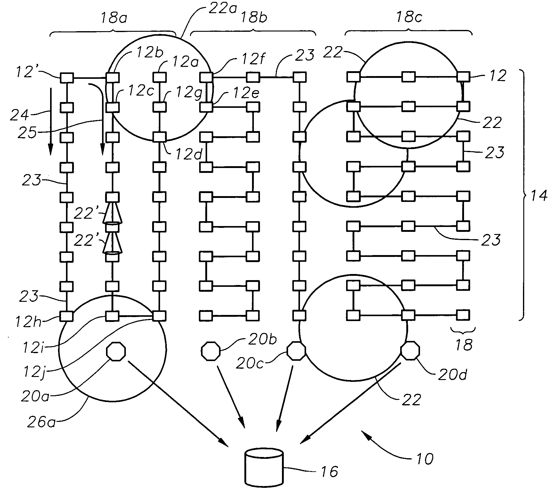
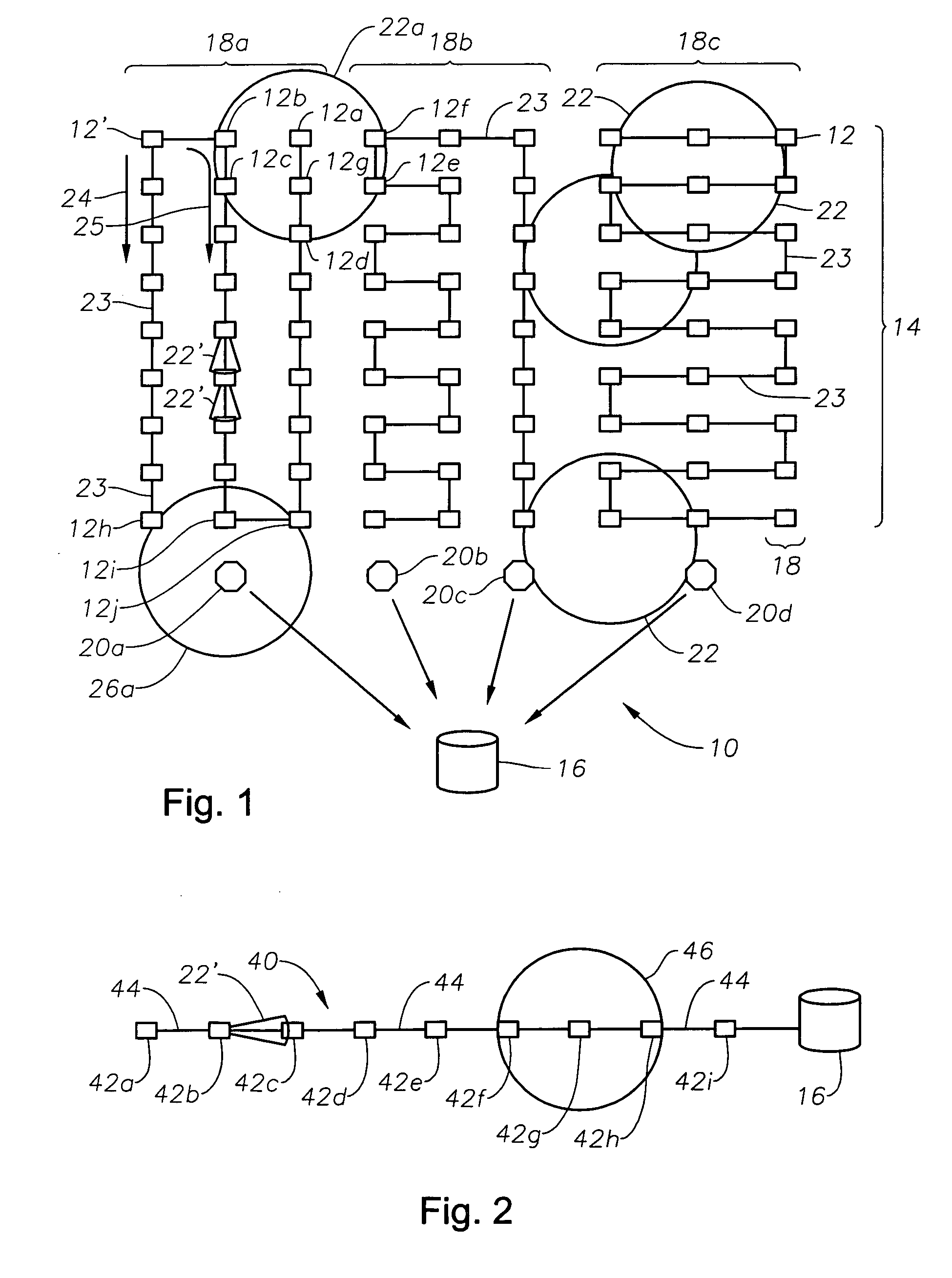
[0024] With reference to FIG. 1, there is shown a seismic data transmission network 10 of the invention. Transmission network 10 is comprised of a plurality of seismic acquisition units 12 spread out in a seismic array 14 and controlled by control station 16. Array 14 is formed of multiple lines 18 of acquisition units 12. Radio transmissions, and in particular, seismic data, are passed from seismic unit 12 to seismic unit 12 as the transmission is bounced through the network 10 to control station 16. In one embodiment of network 10, concentrators 20 are disposed between array 14 and control station 16. While the invention will be described in more detail wi...


PUM


Abstract

The transmission method utilizes multiple seismic acquisition units within an array as intermediate short range radio receivers/transmitters to pass collected seismic data in relay fashion back to a control station. Any one seismic unit in the array is capable of transmitting radio signals to several other seismic units positioned within radio range of the transmitting unit, thus allowing the system to select an optimal transmission path. Utilizing an array of seismic units permits transmission routes back to a control station to be varied as needed. In transmissions from the most remote seismic unit to the control station, each unit within a string receives seismic data from other units and transmits the received seismic data along with the receiving unit's locally stored seismic data. Preferably, as a transmission is passed along a chain, it is bounced between seismic units so as to be relayed by each unit in the array.

Description

BACKGROUND OF THE INVENTION [0001] 1. Field of the Invention [0002] The present invention relates to seismic data acquisition, and more particularly to a method and system for transmitting data between multiple remote stations in an array and a data collection station utilizing a linked relay system to communicate therebetween permitting transmission paths to be altered. [0003] 2. Description of the Prior Art [0004] Seismic exploration generally utilizes a seismic energy source to generate an acoustic signal that propagates into the earth and is partially reflected by subsurface seismic reflectors (i.e., interfaces between subsurface lithologic or fluid layers characterized by different elastic properties). The reflected signals are detected and recorded by seismic units having receivers or geophones located at or near the surface of the earth, thereby generating a seismic survey of the subsurface. The recorded signals, or seismic energy data, can then be processed to yield informat...

Claims


Application Information

Patent Timeline
Patent Type & Authority Applications(United States)
IPC IPC(8): G01VG01V1/22G01V1/28G06F19/00
CPCG01V1/223G01V1/22G01V1/226G01V1/003G01V1/00
Inventor RAY, CLIFFORD H.FISSELER, GLENN D.
Owner MAGSEIS FF LLC
Why Eureka
Try Eureka