Deposition mask and manufacturing method thereof

a technology of mask and manufacturing method, applied in the field of deposition mask, can solve problems such as difficulty in positioning, and achieve the effect of improving the position precision of passage holes

Inactive Publication Date: 2005-06-02
SONY CORP
View PDF6 Cites 49 Cited by
  • Summary
  • Abstract
  • Description
  • Claims
  • Application Information

AI Technical Summary

Benefits of technology

[0005] The present invention relates to a deposition mask used for a deposition process in a manufacturing process of an electronic component, a semiconductor, a reflective film of an optical component, an organic light-emitting

Problems solved by technology

However, with the conventional deposition mask, it is difficult to position the passage hole 131 at a

Method used


Image

  • Deposition mask and manufacturing method thereof
  • Deposition mask and manufacturing method thereof
  • Deposition mask and manufacturing method thereof

Examples


Embodiment Construction

[0022] The present invention relates to a deposition mask used for a deposition process in a manufacturing process of an electronic component, a semiconductor, a reflective film of an optical component, an organic light-emitting device and the like.

[0023] Embodiments of the invention will be hereinafter described in detail with reference to the drawings.

[0024] Before a deposition mask according to an embodiment of the invention is described, first, a concrete example of a display unit manufactured by this mask will be hereinafter described.

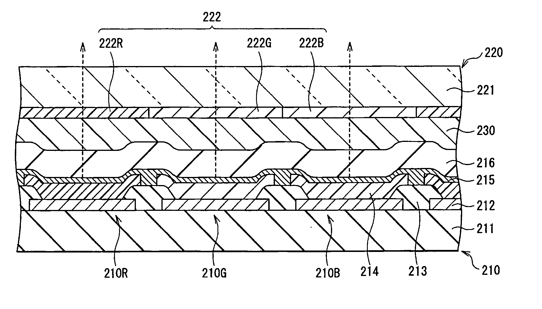
[0025] This display unit is used, for example, as an ultrathin organic light emitting display. As shown in FIG. 3, a driving panel 210 and a sealing panel 220 are placed opposite, and their whole faces are bonded together by an adhesive layer 230 made of, for example, a thermosetting resin. In the driving panel 210, for example, an organic light-emitting device 210R for emitting red light, an organic light-emitting device 210G for emitting gree...


PUM

PropertyMeasurementUnit
Sizeaaaaaaaaaa
Shapeaaaaaaaaaa
Areaaaaaaaaaaa

Abstract

A deposition mask with which position precision of a passage hole is improved and deposition can be conducted precisely and a manufacturing method thereof are provided. A mask body made of a metal thin film is fixed and tightly mounted on a frame body having an opening. The mask body has at least one pattern region including a plurality of passage holes for letting through a deposition material, a stress relaxation region including a plurality of fine holes provided at the periphery of the pattern region, and a holding region provided at the periphery of the stress relaxation region. The mask body is tightly mounted on the frame body at a holding region.

Description

CROSS REFERENCES TO RELATED APPLICATIONS [0001] This application claims priority to Japanese Patent Application No. P2003-403655 filed on Dec. 2, 2003, the disclosure of which is incorporated by reference herein. BACKGROUND OF THE INVENTION [0002] The present invention relates to a deposition mask used for a deposition process in a manufacturing process of an electronic component, a semiconductor, a reflective film of an optical component, an organic light-emitting device and the like. [0003] Conventionally, vacuum deposition method with a deposition mask is widely used for manufacturing an organic light-emitting device using a low molecular weight material. As shown in FIG. 1, the deposition mask has, for example, a construction wherein a mask body 120 made of a metal thin film is mounted at a certain tension on a frame body 110. The mask body 120 has a pattern region 130 consisting of plenty of passage holes 131 for letting through a deposition material. [0004] However, with the c...

Claims


Application Information

Patent Timeline
IPC IPC(8): C23C14/04C23C14/12H05B33/10H01L27/32H01L51/00H01L51/50
CPCC23C14/042H01L51/0011H01L27/3211C23C14/12H10K59/35H10K71/166H05B33/10
Inventor HAGIWARA, NOBUONAGASAKI, HIDEOMORI, TSUTOMUHIRATA, TATSUSHIROYAGI, HAJIME
Owner SONY CORP
Why Eureka
Try Eureka