Vehicle air conditioner

a technology for air conditioners and vehicles, applied in the field of vehicles, can solve the problems of increasing the difficulty of reducing the size of the interior air conditioner uni

Inactive Publication Date: 2005-06-02
DENSO CORP
View PDF6 Cites 30 Cited by
  • Summary
  • Abstract
  • Description
  • Claims
  • Application Information

AI Technical Summary

Benefits of technology

[0017] For example, the air flow switching means includes a first bypass passage through which air flows while bypassing the first heat exchanger, a first switching member for opening and closing the first bypass passage, a second bypass passage through which air flows while bypassing the second heat exchanger, and a second switching member for opening and closing the second bypass passage. Generally, the first bypass passage is provided at one side of the first heat exchanger in the air conditioning case, and the second bypass passage is provided in the air conditioning c

Problems solved by technology

Therefore, it is difficult to reduce the size of the interior air-conditioning unit.
However, in this case, because the three heat exchangers are used in the inte

Method used


Image

  • Vehicle air conditioner
  • Vehicle air conditioner
  • Vehicle air conditioner

Examples


first embodiment

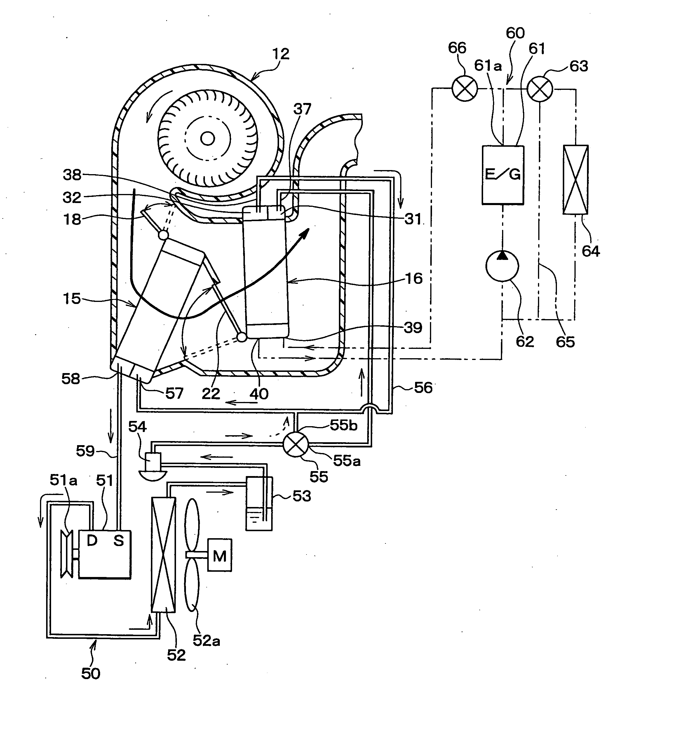
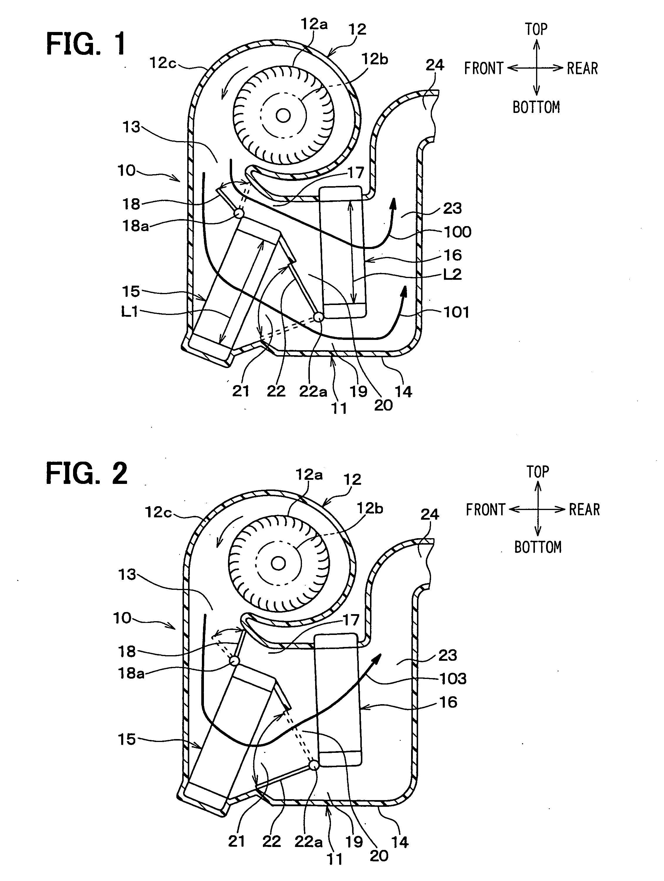
[0028] The first embodiment of the present invention will be now described with reference to FIGS. 1-8. In the first embodiment, an interior air-conditioning unit 10 is mounted in a vehicle in an arrangement state shown in FIGS. 1-4.

[0029] The interior air-conditioning unit 10 includes an air-conditioning unit portion 11 having therein heat exchangers, and a blower portion 12 disposed at an upper side of the air-conditioning unit portion 11. The blower portion 12 is constructed with a centrifugal fan 12a, an electrical motor 12b for driving the centrifugal fan 12a, and a scroll casing 12c for accommodating the centrifugal fan 12.

[0030] A suction port (not shown) of the centrifugal fan 12a is formed on a side wall of the scroll casing 12c in a vehicle right-left direction (face-back direction of paper in FIGS. 1-4), and an inside / outside air switching box (not shown) is provided to be connected to the suction port. The inside / outside air switching box has an outside air introductio...

second embodiment

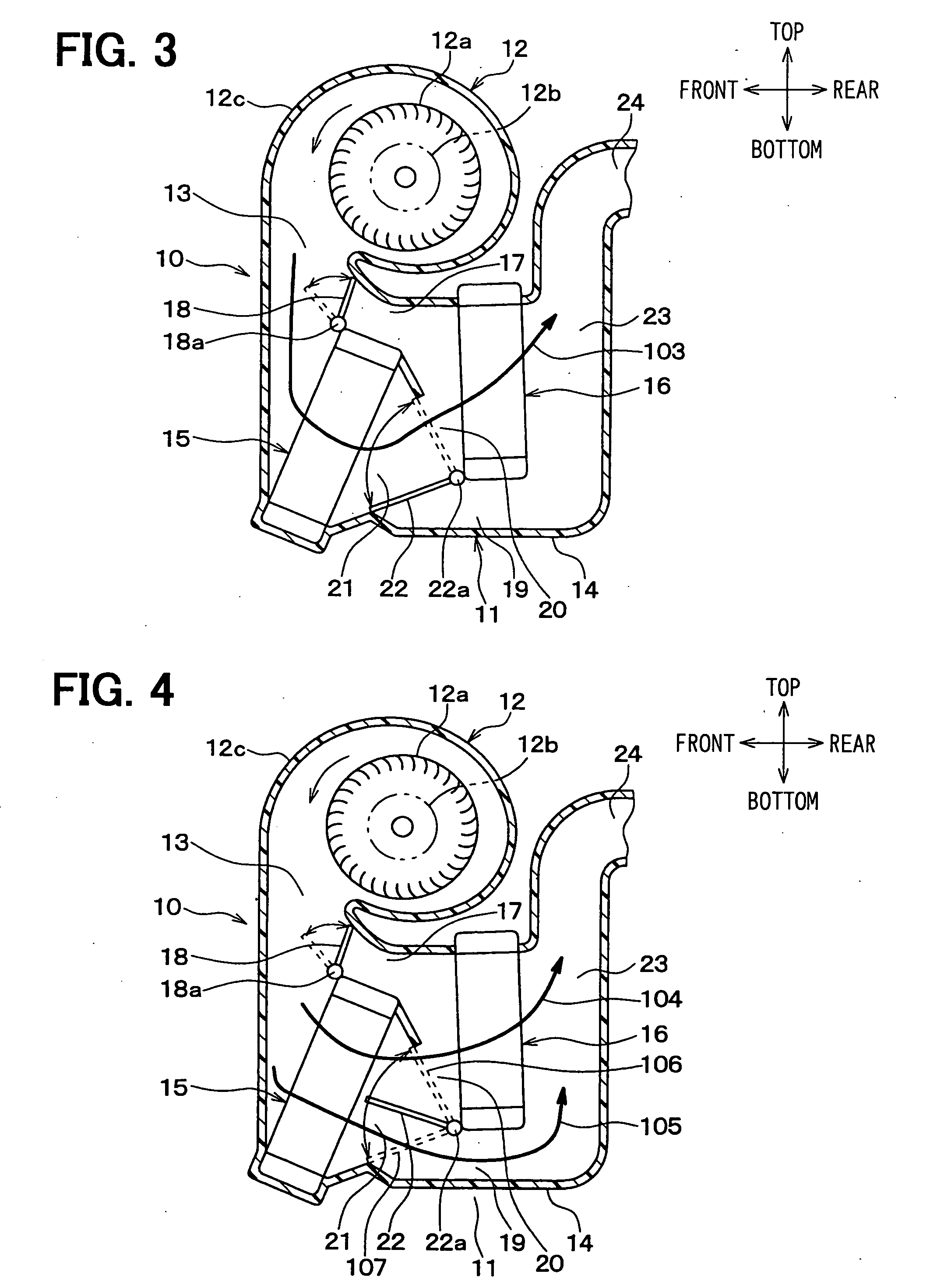
[0089] In the above-described first embodiment, when the temperature control mode shown in FIG. 4 is set, the first bypass door 18 is operated to the solid line position to fully close the first bypass passage 17, and the rotation position (i.e., opening degree) of the second bypass door 22 is changed so that the temperature of the air blown into the passenger compartment is controlled to a target temperature in the predetermined temperature range.

[0090] In the second embodiment, as shown in FIG. 9, when the temperature control state is set, the second bypass door 22 is operated to the solid line position to fully close the communication passage 20, and the rotation position (opening degree) of the first bypass door 18 is changed so that the temperature of air blown into the passenger compartment is controlled.

[0091] According to the second embodiment, a part of air blown by the blower 10 bypasses the cooling heat exchanger 15 to flow through the first bypass passage 17 (shown by ...


PUM


Abstract

In a vehicle air conditioner, a cooling heat exchanger for cooling air is arranged in the air conditioning case, and a cooling/heating switching heat exchanger is arranged at a downstream air side of the cooling heat exchanger in the air conditioning case. A first bypass passage is provided at one side of the cooling heat exchanger in the air conditioning case, so that air flows through the first bypass passage while bypassing the cooling heat exchanger. A second bypass passage is provided at one side of the cooling/heating switching heat exchanger in the air conditioning case on an opposite side of the first bypass passage with respect to the first heat exchanger, so that air flows through the second bypass passage while bypassing the cooling/heating switching heat exchanger. Accordingly, a size of the air conditioner can be effectively decreased while a maximum cooling capacity can be sufficiently obtained.

Description

CROSS REFERENCE TO RELATED APPLICATION [0001] This application is based on Japanese Patent Application No. 2003-402909 filed on Dec. 2, 2003, the disclosure of which is incorporated herein by reference. FIELD OF THE INVENTION [0002] The present invention relates to a vehicle air conditioner in which a size of an interior air-conditioning unit can be effectively reduced. BACKGROUND OF THE INVENTION [0003] In a vehicle air conditioner described in U.S. Pat. No. 6,431,257 (corresponding to JP-A-2001-105830), a heating heat exchanger, a cool air bypass passage and an air mixing door are suitably arranged with respect to a cooling heat exchanger constructed of an evaporator of a refrigerant cycle, so that a size of an interior air-conditioning unit is reduced. However, in this vehicle air conditioner, a maximum cooling capacity to be necessary is obtained only using the single cooling heat exchanger. Accordingly, the size of the cooling heat exchanger necessarily becomes larger when, the...

Claims


Application Information

Patent Timeline
IPC IPC(8): B60H1/00B60H1/08B60H1/32F25D3/02F25D17/06F28D1/04F28D7/00
CPCB60H1/0005B60H1/00057B60H1/00321B60H1/00885F28D7/0025B60H2001/00164B60H2001/00949F28D1/0426F28D1/0435B60H2001/00107
Inventor ITO, KOJISHINDO, TOMOHIDE
Owner DENSO CORP
Why Eureka
Try Eureka