Control of a pressure exchanger by displacement of an injection valve member

a technology of pressure exchanger and injection valve, which is applied in the direction of fuel injection apparatus, machine/engine, feed system, etc., can solve the problem of limited pressure level in the current use of accumulator injection system

Inactive Publication Date: 2005-06-02
ROBERT BOSCH GMBH
View PDF1 Cites 12 Cited by
  • Summary
  • Abstract
  • Description
  • Claims
  • Application Information

AI Technical Summary

Problems solved by technology

For strength reasons, the achievable pressure level in accumulator injection systems currently in use is limited to approximately 1600 bar at this time.

Method used


Image

  • Control of a pressure exchanger by displacement of an injection valve member
  • Control of a pressure exchanger by displacement of an injection valve member
  • Control of a pressure exchanger by displacement of an injection valve member

Examples


embodiment versions

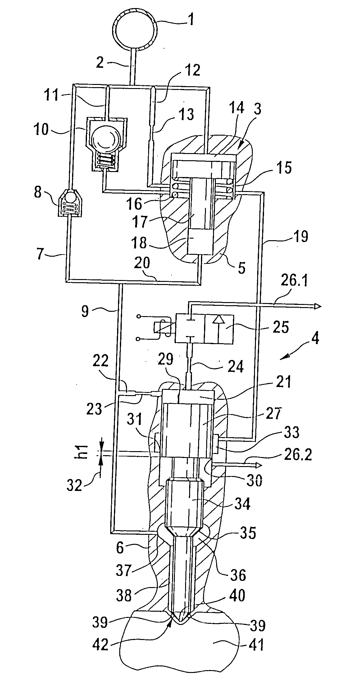
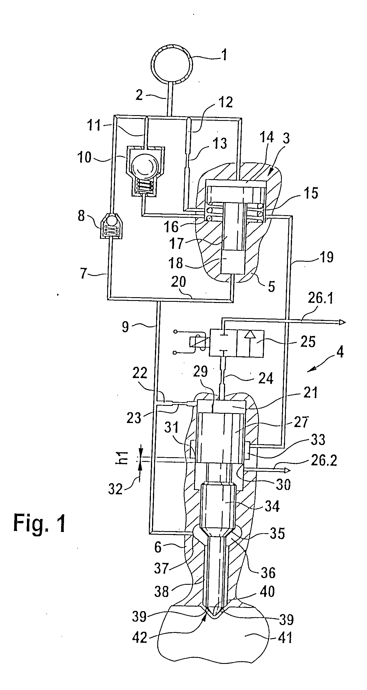
[0012]FIG. 1 shows a first embodiment version of a pressure booster that can be actuated by an injection valve element, depicted in a first state in which the control chamber of the pressure booster is disconnected from the return, i.e. from the low-pressure region of the fuel injection system.

[0013] Starting from a high-pressure source 1, which can be embodied, for example, as a high-pressure accumulator (common rail), a high-pressure inlet 2 extends to a pressure booster 3. The high-pressure inlet 2 has a high-pressure line 7 that can contain a check valve 8. Parallel to the high-pressure line 7, the high-pressure inlet 2 from the high-pressure source 1 acts on a parallel branch 11 that can contain a filling valve 10. Another branch 12 extends parallel to it, which contains a throttle restriction 13. The first parallel branch that contains the filling valve 10 and the additional parallel branch 12 that contains the throttle restriction 13 feed into a control chamber 15 of the pre...


PUM


Abstract

A device for injecting fuel into a combustion chamber of an internal combustion engine, including an injector body which contains an injection valve element which can be actuated through pressurization / pressure relief of a control chamber by means of a control valve. A pressure booster having a piston unit that divides a working chamber from a control chamber of the pressure booster acts on a compression chamber that communicates with a nozzle chamber encompassing the injection valve element. A pressurization or pressure relief of the control chamber of the pressure booster occurs as a function of the stroke motion of the injection valve element.

Description

TECHNICAL FIELD [0001] Both pressure-controlled and stroke-controlled injection systems can be used to supply fuel to combustion chambers of autoignition internal combustion engines. In addition to unit injectors and unit pumps, accumulator injection systems are also used as fuel injection systems. Accumulator (common rail) injection systems advantageously make it possible to adapt the injection pressure to the load and speed of the autoignition internal combustion engine. Achieving high specific outputs and reducing emissions of the autoignition engine generally require the highest possible injection pressure. PRIOR ART [0002] For strength reasons, the achievable pressure level in accumulator injection systems currently in use is limited to approximately 1600 bar at this time. In order to further increase the pressure in accumulator injection systems, common rail systems employ pressure boosters. [0003] DE 199 10 970 A1 relates to a fuel injection apparatus. This fuel injection app...

Claims


Application Information

Patent Timeline
Patent Type & Authority Applications(United States)
IPC IPC(8): F02M47/02F02M57/02F02M47/00F02M59/10F02M61/04F02M63/02
CPCF02M47/027F02M57/025F02M59/105F02M61/042F02M63/0225
Inventor MAGEL, HANS-CHRISTOPH
Owner ROBERT BOSCH GMBH
Why Eureka
Try Eureka