Brush chipper and methods of operating same

a chipper and brush technology, applied in the field of brush chippers, can solve the problems of operator attempting to disable the shut off mechanism, affecting the operation of the same,

Inactive Publication Date: 2005-06-02
VERMEER MFG CO
View PDF16 Cites 0 Cited by
  • Summary
  • Abstract
  • Description
  • Claims
  • Application Information

AI Technical Summary

Problems solved by technology

A problem with prior art devices is that when larger branches are inserted onto the feed table, that means that larger sub-branches will also emanate from such branch.
While these prior art brush chippers operate just fine when smaller branches are fed into the brush chipper, the problem primarily exists during the time that larger or stiffer sub-branches are being fed into the brush chipper.
It is perceived that if the machine is constantly being shut off by the lower feed stop bar when larger branches are being fed into the machine, there is a danger that an operator might attempt to disable the shut off mechanism so that he can continue to finish the job of chipping larger branches without the inconvenience of having the brush chipper shut itself off frequently, i.e. nuisance stops.
Prior art devices do not distinguish between the two.
This can be due to drag caused by a log or the like rubbing against the cutter mechanism.
So merely stopping the feed rollers may not be sufficient to solve the problem.
This could be due to an operator hauling branches to the chipper, moving the chipper to another location, or the operator being distracted for some reason and not using the chipper.
This causes fuel to be used unnecessarily and causes unnecessary wear and tear on the brush chipper.

Method used


Image

  • Brush chipper and methods of operating same
  • Brush chipper and methods of operating same
  • Brush chipper and methods of operating same

Examples


Embodiment Construction

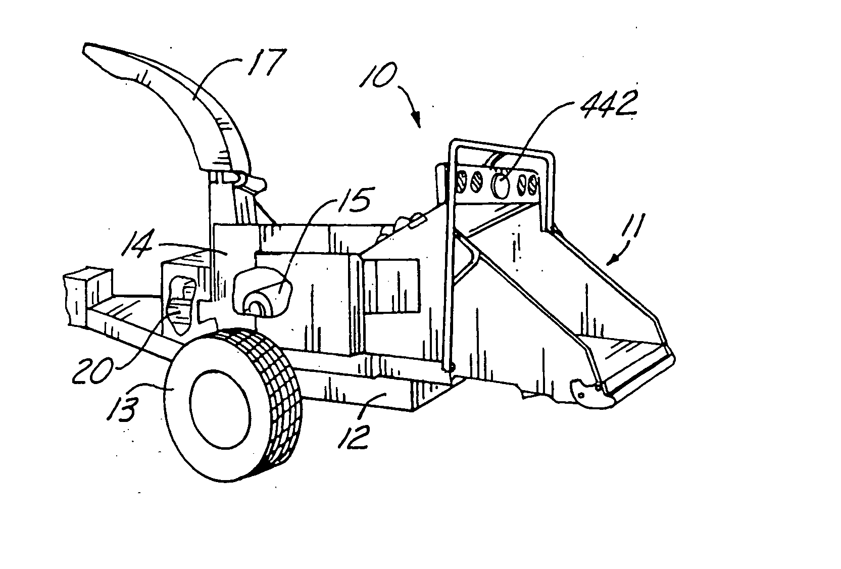
[0063] Referring now to the drawings wherein like reference numerals designate identical or corresponding parts throughout the several views, FIG. 1 shows a brush chipper (10) constructed in accordance with the present invention and having a feed table (11) on the rear thereof. A frame (12) has wheels (13) rotatably attached thereto to permit the brush chipper (10) to be moved from place to place. A housing (14) has cutters (15) which cut brush that enters the feed table (11), which brush is pulled therethrough by feed rollers (16) and delivers the brush to the cutters to cut the brush and throw chips out a discharge chute (17).

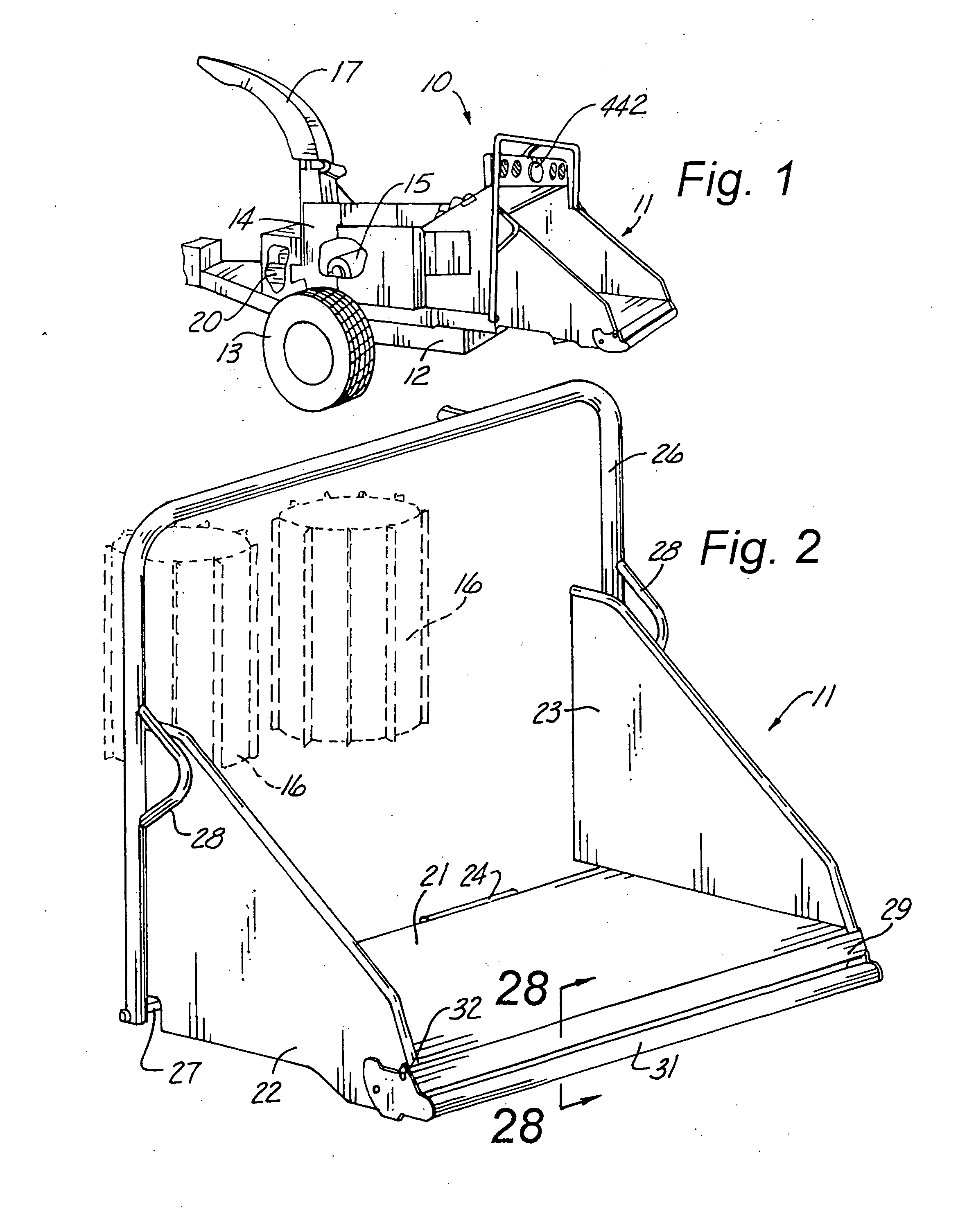
[0064] The feed table (11), as shown in FIGS. 1 and 2, has a bottom portion (21) and side portions (22) and (23). A hinge (24) pivotally attaches the feed table (11) to the frame (12). An upper feed control member (26) is pivotally attached at rod (27) to the frame (12). The feed table (11) is in the operative position shown in FIG. 1, but would be pivoted u...


PUM

PropertyMeasurementUnit
forceaaaaaaaaaa
pressureaaaaaaaaaa
rotationaaaaaaaaaa

Abstract

An improved brush cutter having an upper feed control member with stop, forward, neutral, and reverse positions also has a lower feed stop member with selectable sensitivity. Another aspect of the invention is to predict the feed roller shutoff point according to the rate of engine deceleration. According to another aspect, when the feed rollers stop feeding material into the cutters, to overcome drag on the cutters, a controller stops the feed rollers and then reverses them for a short time, and then reverses the rollers again if the problem is still present. To prevent jamming, a pressure switch senses when oil in a hydraulic motor system for rotating the feed rollers is too high and the controller momentarily reverses the feed rollers and then causes them to go forward, a cycle which can occur several times until the feed rollers are no longer stalled. By another aspect of the invention, the controller senses characteristics of the brush cutter and chooses an operating system based on the characteristics sensed. The controller can also sense if the brush chipper has not been used for a predetermined period of time and automatically reduce the idle speed of the engine until the brush chipper is used again, and then automatically return the engine to a normal idle speed before the feed rollers will pull brush into the brush chipper.

Description

CROSS-REFERENCE TO RELATED APPLICATIONS [0001] This application contains disclosure from and claims the benefit under Title 35, United States Code, § 119(e) of the following U.S. Provisional Application: U.S. Provisional Application Ser. No. 60 / 246,670 filed Nov. 8, 2000, entitled METHOD AND APPARATUS FOR OPERATING A BRUSH CHIPPER USING PREDICTABILITY OF RPM, REVERSING OF FEED ROLLS, OPTIMIZING ENGINE RPM, OVERCOMING JAMMING & SELF DIAGNOSIS.STATEMENT REGARDING FEDERALLY SPONSORED RESEARCH OR DEVELOPMENT [0002] Not Applicable BACKGROUND OF THE INVENTION [0003] 1. Field of the Invention [0004] One aspect of the present invention relates generally to brush chippers which have a manually controlled upper feed stop member with four positions, which sequentially from forward to rear of the upper feed stop member are stop, forward, neutral and reverse, and a lower feed stop member which serves to shut off the feed mechanism of the brush chipper when it is moved forwardly by a predetermine...

Claims


Application Information

Patent Timeline
Patent Type & Authority Applications(United States)
IPC IPC(8): A01G3/00B02C18/22B02C23/04
CPCA01G3/002B02C18/2283B02C23/02B27L11/002B02C2018/164B02C2201/066B02C23/04
Inventor STELTER, MARK ROBERTO'HALLORAN, JAMES L.GABLER, DENNIS K.KERNWEIN, JEFFREY D.
Owner VERMEER MFG CO
Why Eureka
Try Eureka