Device for optical signal transmission between two units movable relative to each other

a technology of optical signal transmission and moving unit, which is applied in the direction of fiber transmission, transmission, electromagnetic transmission, etc., can solve the problems of high attenuation result of many notches along the light-guiding medium, unsuitable coupling signal systems, and unusually expensive optical components, etc., to achieve small demands on the dynamic ratio of optical receivers and high attenuation

Inactive Publication Date: 2005-06-02
SCHLEIFRING & APPBAU
View PDF12 Cites 6 Cited by
  • Summary
  • Abstract
  • Description
  • Claims
  • Application Information

AI Technical Summary

Benefits of technology

[0009] The invention is based on the object of providing an optical data-transmission system which makes only small demands on the dynamic ratio of an optical receiver, even with transmission media having high attenuations. In accordance with the present invention, this object is achieved by a device for transmitting optical signals between at least two units movable relative to each other, comprising a first unit comprising a light guide disposed along a track of movement; a second unit comprising a coupler movable along the light guide for coupling optical signals into or out of the light guide; at least one light source; at least one light sink; and at least one optical path between the light source and the light sink; the light source(s) and the light sink(s) being optionally assigned to the first unit and the second unit, respectively, or to the second unit and the first unit, respectively; at least one variable optical attenuating member being provided in the optical path for maintaining an optical attenuation of the optical path within a given range of tolerance.
[0010] In accordance with the present invention, the above object is also achieved by a device for transmitting optical signals between at least two units movable relative to each other, comprising a first unit comprising a light guide disposed along a track of movement; a second unit comprising a coupler movable along the light guide for coupling optical signals into or out of the light guide; at least one light source; at least one light sink; and at least one optical path between the light source and the light sink; the light source(s) and the light sink(s) being optionally assigned to the first unit and the second unit, respectively, or to the second unit and the first unit, respectively; the at least one light source comprising means for electrically controlling an emitted optical power; and a control unit being provided for controlling the optical power of the light source in such manner that the optical power at an input of the light sink of an assigned optical path is within a given range of tolerance.

Problems solved by technology

However, systems of this kind are not suitable for coupling signals in or out laterally at arbitrary positions on a light-guiding fiber.
However, if a long path of movement is required, as is the case with crane systems or even rotary transmission systems of large diameter, then a very high attenuation results from the many notches along the light-guiding medium.
Therefore, for long transmission paths this transmission system is practicable only with unusually expensive optical components involving large outlay.

Method used


Image

  • Device for optical signal transmission between two units movable relative to each other
  • Device for optical signal transmission between two units movable relative to each other

Examples


Embodiment Construction

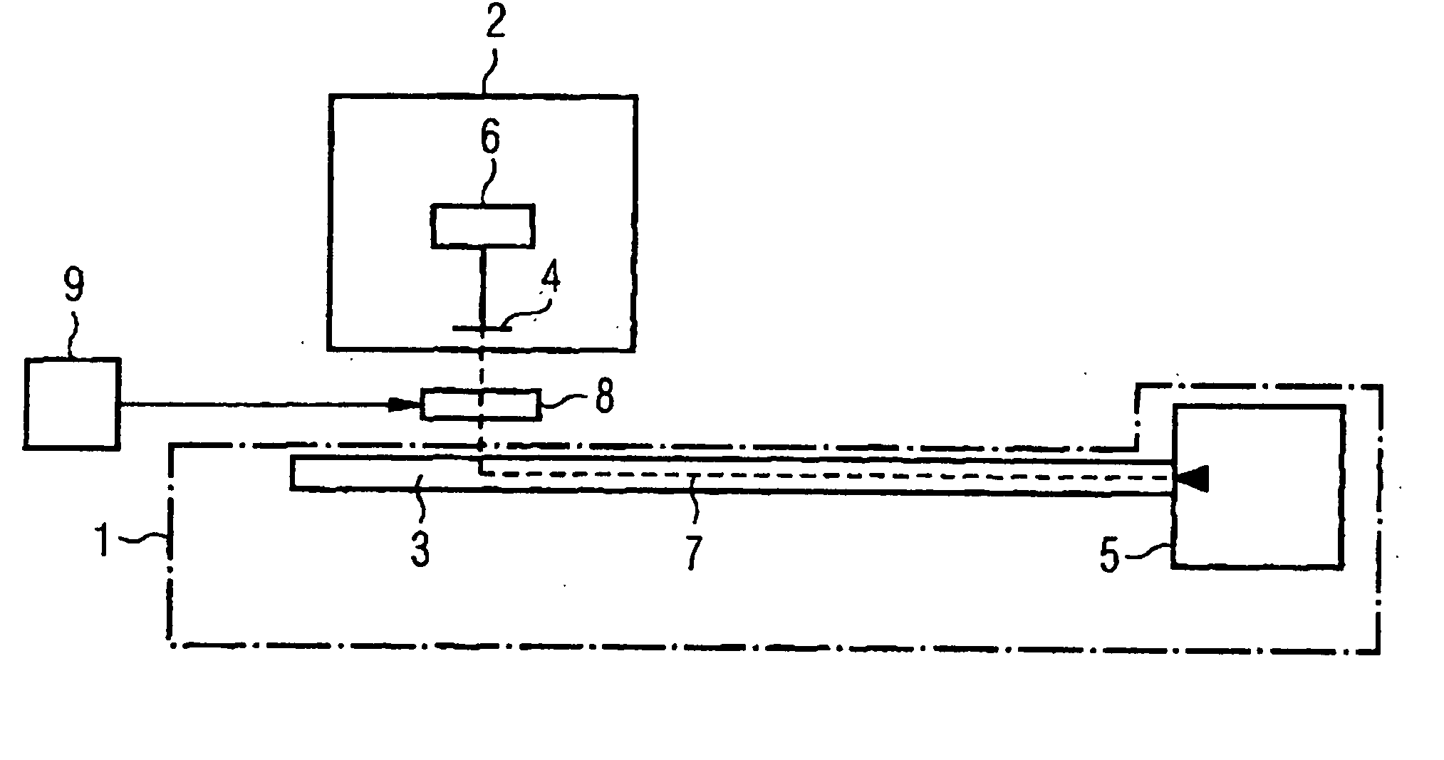
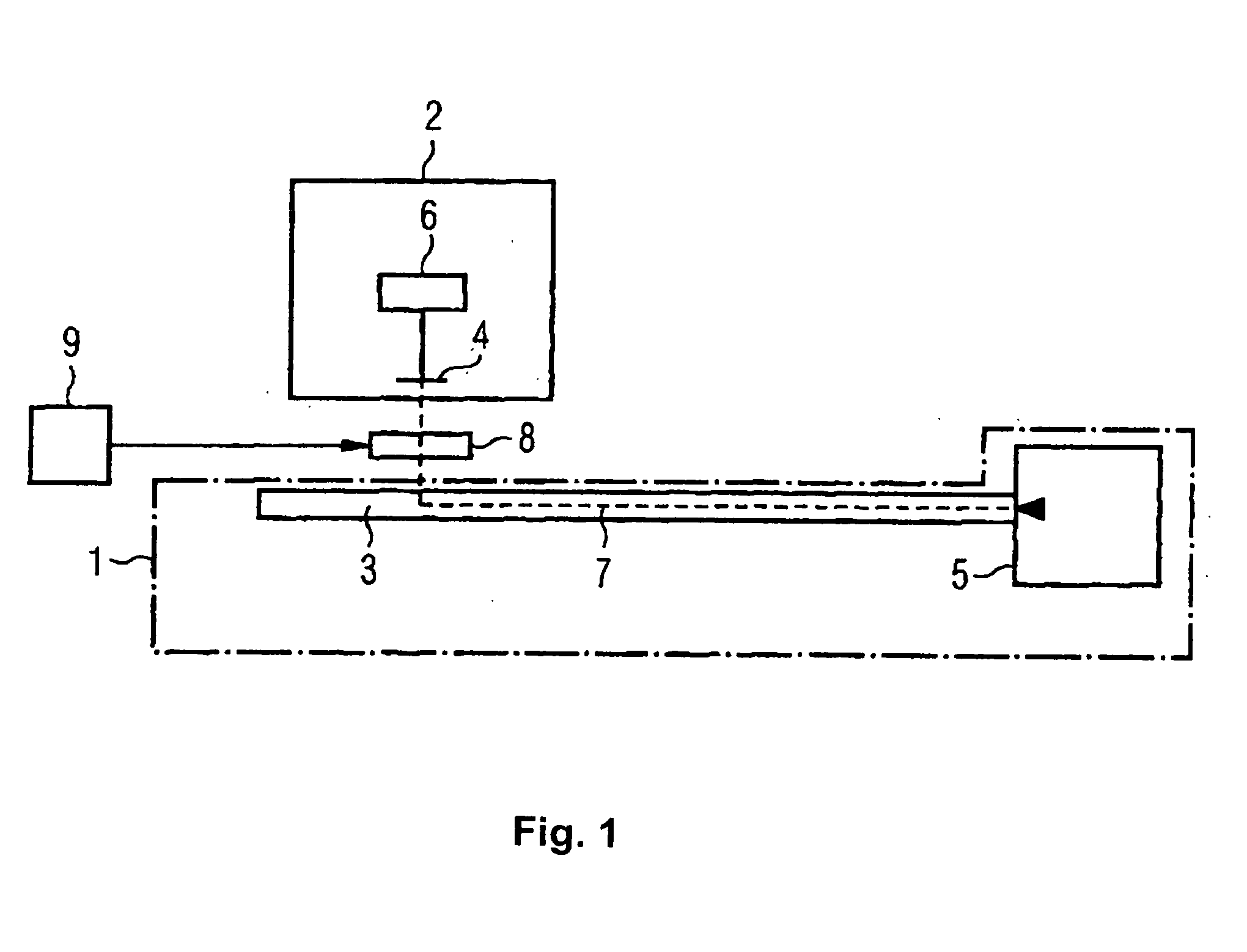
[0023] The transmission device in accordance with the invention comprises at least one first unit which has a light guide disposed along a path of movement. Furthermore, at least one second unit is provided which has a coupler that is movable along the light guide for coupling optical signals into or out of the light guide. The generation of the light is effected by at least one light source. The light transmitted by the device is finally passed to a light sink.

[0024] The manner of operation of the device according to the invention is independent from the direction of transmission of the light. Therefore one or a plurality of light sources, or one or a plurality of light sinks, may be assigned optionally to the first unit or also to the second unit. Therefore, basically two optical paths may be constructed.

[0025] In the first optical path the light source couples light into the light guide of the first unit. This light is coupled out by a coupler of the second unit and passed to a...


PUM


Abstract

A device for transmitting optical signals between at least two units movable relative to each other comprises an adjustable attenuating member for achieving a system attenuation which is independent of the relative position of the units movable relative to each other.

Description

CROSS REFERENCE TO RELATED APPLICATIONS [0001] This application is a continuation of pending International Application No. PCT / DE03 / 01535 filed May 13, 2003, which designates the United States and claims priority from pending German Application No. 102 22 221.5 filed May 16, 2002.BACKGROUND OF THE INVENTION [0002] 1. Field of the Invention [0003] The invention relates to a device for optical transmission of data by means of light guides, in which a transmitter and / or a receiver can be moved or differently positioned along a light guide. [0004] Devices of this kind are utilized for example in a linear configuration in crane systems or other conveyor systems for transmitting data between a movable crane and a stationary control unit. Another field of application of these data transmission systems in a circular configuration is a transmission between parts that are rotatable relative to each other, such as, for example, in a computer tomograph between a rotor for supporting an X-ray tu...

Claims


Application Information

Patent Timeline
Patent Type & Authority Applications(United States)
IPC IPC(8): G02B6/36H04B10/00
CPCH04B10/22G02B6/3604H04B10/25H04B10/801
Inventor SCHILLING, HARRY
Owner SCHLEIFRING & APPBAU
Why Eureka
Try Eureka