Driving circuit of current-driven device current-driven apparatus, and method of driving the same

a technology of current-driven devices and driving circuits, which is applied in the direction of television systems, instruments, pulse techniques, etc., can solve the problems of insufficient write operations, degraded image quality, and forgoing conventional techniques, so as to reduce the time necessary for pre-charge and reduce the time necessary for potential settlement

Inactive Publication Date: 2005-06-02
RENESAS ELECTRONICS CORP +1
View PDF8 Cites 17 Cited by
  • Summary
  • Abstract
  • Description
  • Claims
  • Application Information

AI Technical Summary

Benefits of technology

[0026] It is an object of the present invention to provide a driving circuit of a current-driven device which can settle the potential of a current controlling transistor of the current-driven device quickly and can write a signal accurately, a current-driven apparatus having this driving circuit and a current-driven device, and a method of driving the same.

Problems solved by technology

On this account, excessive write time can result in insufficient write operations, with the problem of degraded image quality.
The foregoing conventional technique, however, has the following problems.
The settling time of the input potential of the voltage follower amplifier is thus becoming increasingly long.
Specifically, trailing defects can occur from writing failures, for example.

Method used


Image

  • Driving circuit of current-driven device current-driven apparatus, and method of driving the same
  • Driving circuit of current-driven device current-driven apparatus, and method of driving the same
  • Driving circuit of current-driven device current-driven apparatus, and method of driving the same

Examples


first embodiment

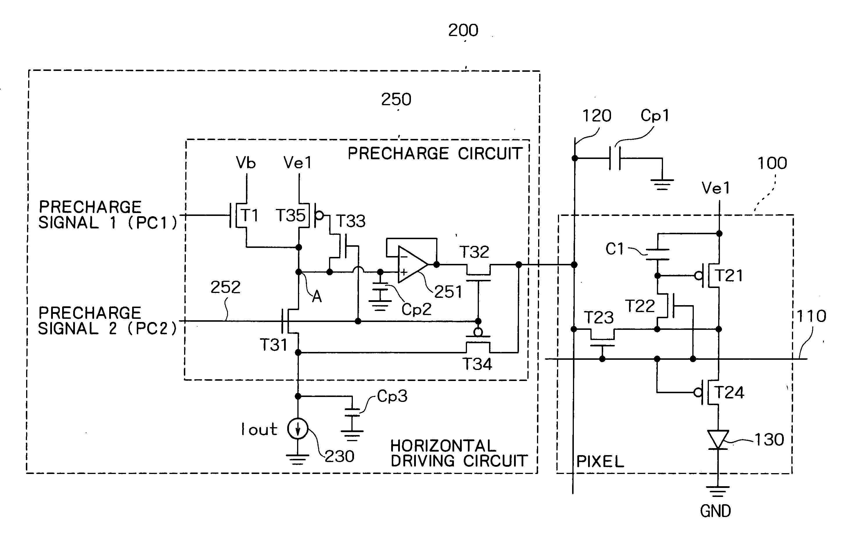
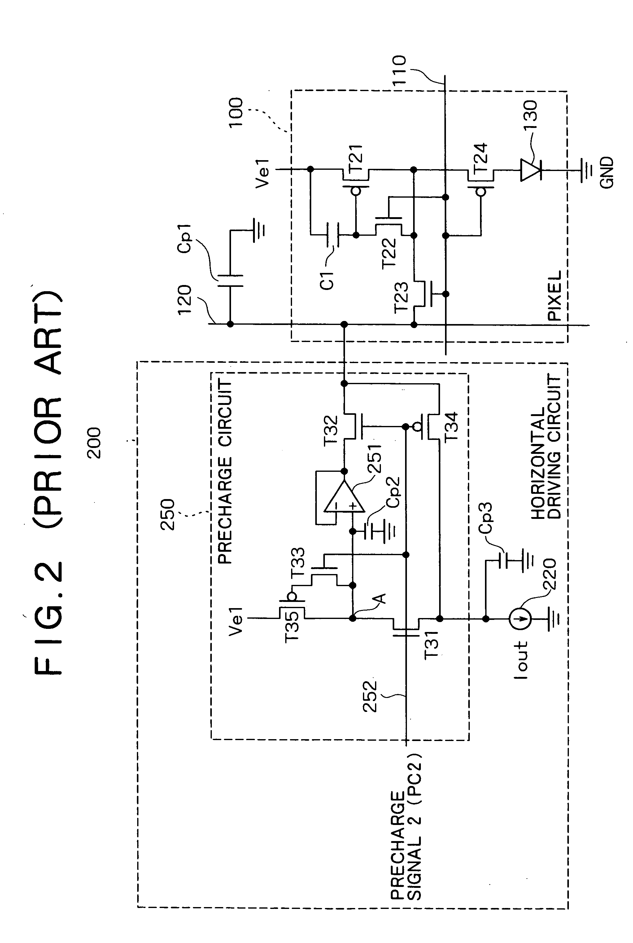
[0072] Hereinafter, embodiments of the present invention will be described concretely with reference to the accompanying drawings. Initially, description will be given of the present invention. The current-driven apparatus according to the present embodiment is an organic EL display. FIG. 4 is a block diagram showing a horizontal driving circuit of the organic EL display according to the present embodiment. FIG. 5 is a block diagram showing a D / I conversion unit of the horizontal driving circuit shown in FIG. 4. FIG. 6 is a block diagram showing a one-output D / I conversion unit of the D / I conversion unit shown in FIG. 5. FIG. 7 is a circuit diagram showing the data creation circuit shown in FIG. 6. FIG. 8 is a block diagram showing a 1-bit D / I conversion unit shown in FIG. 6. FIG. 9 is a circuit diagram showing the D / I conversion unit and a precharge circuit for each single data line, and a pixel circuit for each single pixel in the organic EL display according to the present embodi...

second embodiment

[0137] In the foregoing second embodiment, the potential of the node A is initialized to the level-one potential by means of the reference potential Vps. In this method, however, the initialization potential may be affected by characteristic variations of the driving transistor T35. More specifically, even if the reference potential Vps is set equal to the level-one potential determined by the design value of the driving transistor T35, the level-one potential of the driving transistor T35 may deviate from the design value in actual products. In such cases, the level-one potential of the actual driving transistor T35 can deviate from the reference potential Vps. Then, in the precharge circuit initialization period, the potential of the node A is initialized to the reference potential Vps. When the precharge output potential is the level-one potential, this deviation must therefore be corrected, requiring time for settlement. Incidentally, the characteristic variations tend to increa...

third embodiment

[0147] Then, in the precharge period, the precharge signal PC2 is at high level. This turns off the switching P-channel transistors T2 and T4, so that a current flows through the driving P-channel transistor T35 alone, not the driving P-channel transistor T3. In other respects than those described above, the operation of the present embodiment is the same as that of the foregoing

[0148] According to the present embodiment, the node A is initialized by the current having an intensity of (n×Ips). As compared to the foregoing third embodiment, the initialization can thus be performed more quickly. The effects of the present embodiment other than described above are the same as those of the foregoing third embodiment.


PUM


Abstract

A precharge circuit is provided with an N-channel transistor intended for switching. A reference potential is applied to either one of the source and drain of this N-channel transistor. The other of the source and drain is connected to a node. A precharge signal is applied to the gate of the N-channel transistor. The reference potential is set to a precharge output potential for the case of displaying black on a pixel, i.e., the potential when a minimum current flows through a P-channel transistor connected to the other of the source and drain of the N-channel transistor.

Description

BACKGROUND OF THE INVENTION [0001] 1. Field of the Invention [0002] The present invention relates to a driving circuit of a current-driven device for driving a current-driven device which is driven by supply of an electric current, a current-driven apparatus having this driving circuit and a current-driven device, and a method of driving this current-driven apparatus. [0003] The present invention is applicable to an organic EL display, as well as such current-driven displays as an inorganic EL display and an LED, such current-driven memories as an MRAM, and driving circuits thereof. [0004] 2. Description of the Related Art [0005] Current-driven apparatuses which are controlled in operation by electric currents supplied thereto have been developed heretofore. Among such current-driven apparatuses is an organic electro luminescence (EL) display. [0006] With the advance of development, organic EL devices to be used in organic EL displays have improved in efficiency, contributing to red...

Claims


Application Information

Patent Timeline
Patent Type & Authority Applications(United States)
IPC IPC(8): H01L51/50G09G3/20G09G3/30G09G3/32H03B1/00H03K17/00H03K17/687H04N3/00H04N5/70H05B33/14
CPCG09G3/3241G09G3/325G09G3/3283G09G2320/0223G09G2310/0248G09G2310/027G09G2300/0842
Inventor SHIMODA, MASAMICHIABE, KATSUMIIGUCHI, KOICHI
Owner RENESAS ELECTRONICS CORP
Why Eureka
Try Eureka