Cooling array

a technology of cooling arrays and components, applied in the field of cooling arrays, can solve the problems of increasing the number of built-in components and the inability to change the structure of the cooling arrangement in a simple manner, and achieve the effect of simple manner

Inactive Publication Date: 2005-06-02
RITTALWERK RUDOLF LOH GMBH & CO KG
View PDF18 Cites 3 Cited by
  • Summary
  • Abstract
  • Description
  • Claims
  • Application Information

AI Technical Summary

Benefits of technology

[0009] It is one object of this invention to provide a cooling array of the type mentioned above but which makes ...

Problems solved by technology

It is thus not possible to change the structure of the cooling arrangement i...

Method used


Image

  • Cooling array
  • Cooling array

Examples


Embodiment Construction

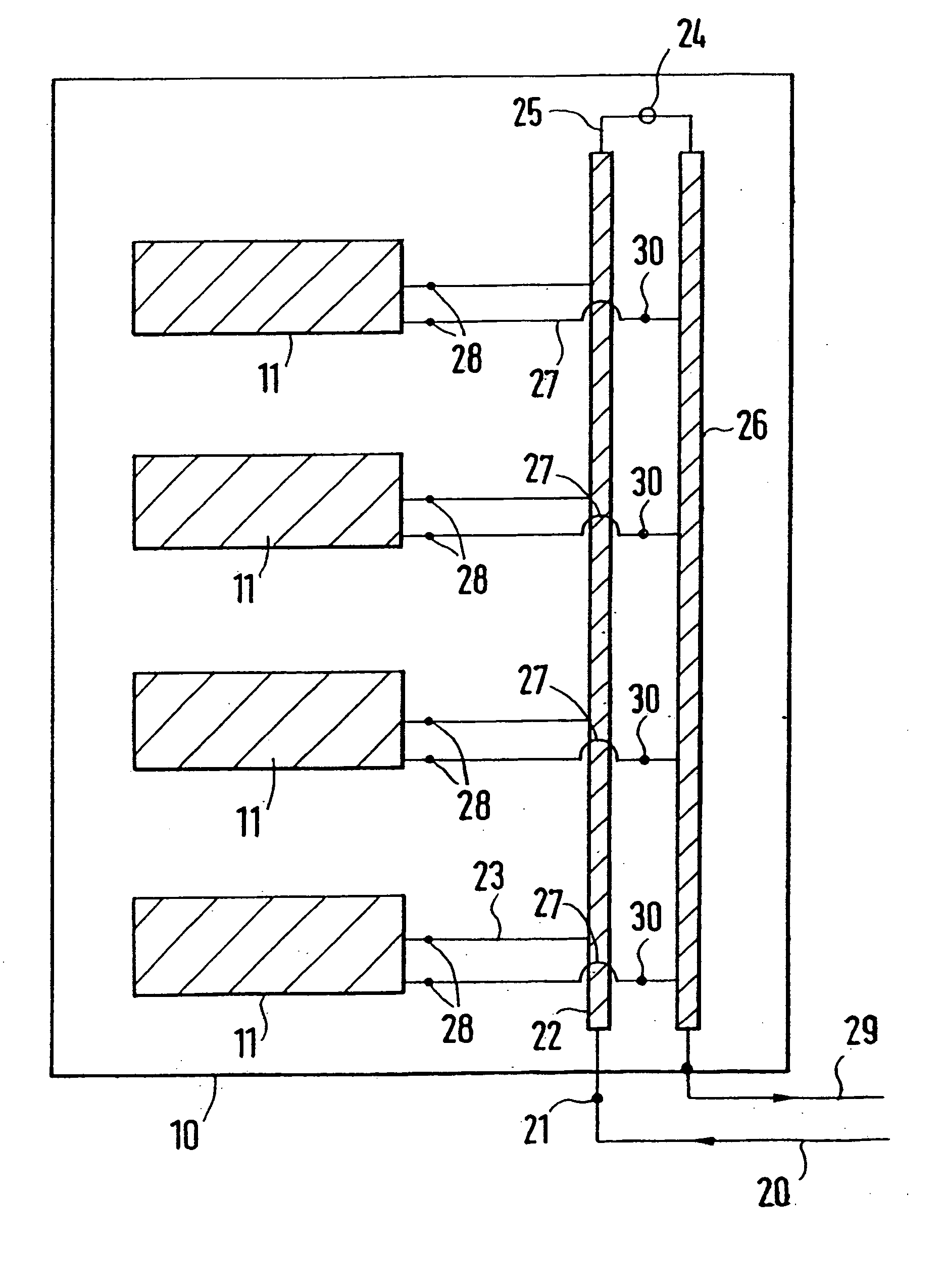
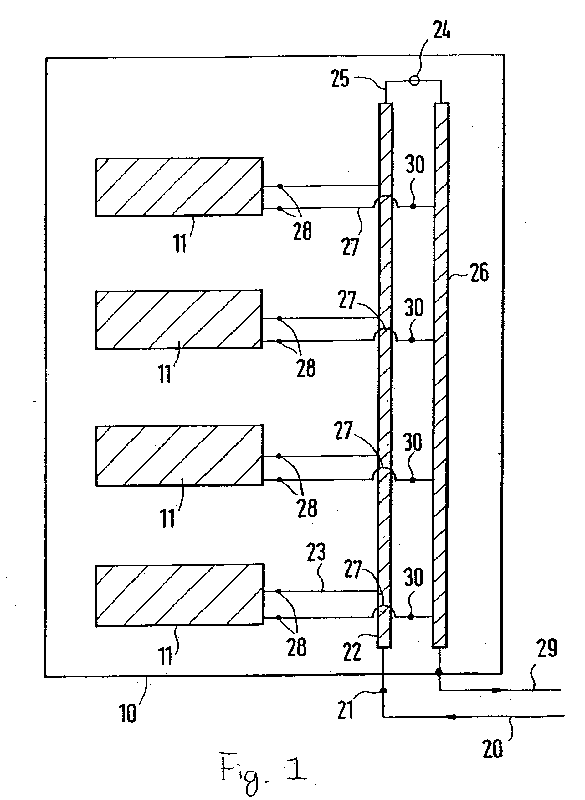
[0022] The drawing shows a cooling array in a schematic representation in which a vertically extending inflow line 22 and an outflow line 26 are arranged in a housing 10. Built-in electrical components 11 are placed inside the housing 10 and contain heat sources which are to be cooled. Respectively, one component inlet line 23 branches off the inflow line 22, and respectively one component outflow line 27 off the outflow line 26. In this case the built-in electrical components 11, which are switched parallel with each other, are connected to the inflow line 22 or the outflow line 26. The connection of the built-in components 11 is provided by coupling connections 28, which can be joined and separated without dripping.

[0023] A governor 30 is integrated into the component outflow line for regulating the cooling output and regulates the amount of flow-through of coolant.

[0024] The inflow line 22 and the outflow line 26 are connected to an inlet line 20, or an outflow line 29 via coup...


PUM


Abstract

A cooling array including a housing accommodating electrical built-in components and an air conditioning device that is connected to a heat source of the electrical built-in components by a coolant-carrying inlet line and a return line. To simply air-condition complex systems having a plurality of electrical built-in components, several device inlet lines come out from the inlet line and device return lines come out from the return line and each electrical built-in component is assigned at least one device inlet line and at least one device return line.

Description

BACKGROUND OF THE INVENTION [0001] 1. Field of the Invention [0002] This invention relates to a cooling array with a housing receiving built-in electrical components and with an air conditioning arrangement, which is connected with a heat source of the built-in electrical components via a coolant-conducting inflow line and an outflow line, wherein several component inlet lines branch off the inflow line and several component outflow lines branch off the outflow line, at least one component inlet line and at least one component outflow line is assigned to a built-in electrical component, and an inlet line and a return flow line branch off the air conditioning arrangement and are connected to the inflow line and the outflow line. [0003] 2. Discussion of Related Art [0004] A cooling arrangement is taught by U.S. Pat. No. 4,514,746. With this known structure the individual lines, which the connection with the air conditioning device and the consumers, for example the built-in electrical...

Claims


Application Information

Patent Timeline
IPC IPC(8): H05K7/20F25D9/00
CPCH05K7/20781
Inventor NICOLAI, MICHAELDORRICH, MARTIN
Owner RITTALWERK RUDOLF LOH GMBH & CO KG
Why Eureka
Try Eureka